Processing apparatus, measuring apparatus, and device manufacturing method

a technology of measuring apparatus and processing method, applied in the direction of fluid pressure control, testing/monitoring control system, instruments, etc., can solve the problems of inability to desirably transfer the mask pattern, the accuracy performance of the exposing apparatus deteriorates, and the throughput of the exposing apparatus is reduced, so as to eliminate the uneven internal temperature and the internal ambience stable

Inactive Publication Date: 2006-01-10
CANON KK
View PDF6 Cites 25 Cited by
  • Summary
  • Abstract
  • Description
  • Claims
  • Application Information

AI Technical Summary

Benefits of technology

[0015]The present invention is made in consideration of the above described problems which must be solved. The primary object of the present invention is to provide a processing apparatus, the internal ambience of which is stable. This is accomplished by creating a flow of the ambient gas in a predetermined direction in the sealed vacuum chamber of the processing apparatus to eliminate the unevenness in the internal temperature of the sealed vacuum chamber while preventing the ambient gas in the vacuum chamber from becoming turbulent.
[0016]Another object of the present invention is to provide a processing apparatus, the internal pressure of the sealed vacuum container of which is controlled with higher accuracy. This is accomplished by effectively compensating for the decrease in the internal pressure of the sealed vacuum chamber.
[0017]Another object of the present invention is to provide a processing apparatus which consumes a much smaller amount of ambient gas, and therefore, costs less to run, compared to conventional apparatus. This is accomplished by storing the ambience gas in its sealed vacuum container, in the ambient gas recirculating system before stopping the apparatus.

Problems solved by technology

In other words, this kind of vacuum loss in an exposure chamber, or a vacuum chamber, is one of the main reasons why the performance of an exposing apparatus deteriorates in accuracy, and also why the throughput of an exposure apparatus reduces.
This kind of local temperature increase deforms the mask and the substrate, making it impossible to desirably transfer the mask pattern.
In addition, the local temperature fluctuation creates a turbulence in the ambience gas in the measurement path of the laser beam projected by the laser interferometry based measuring device in the vacuum chamber, which results in fluctuation in the refractive index of this portion of the ambient gas.
The fluctuation of the refractive index makes it impossible to accurately measure the position of the substrate positioning device with the use of a laser interferometry based measuring device.
However, the above described exposure chamber based on the conventional technologies has a problem, even though it can reduce unevenness in temperature in the chamber by eliminating local temperature increase, and therefore, the ambient gas in the chamber is prevented from becoming turbulent.
The problem is, if the fan of the air conditioner is disposed more than a certain distance away from the exposing portion, the velocity of the down flow created in the chamber does not reach a predetermined velocity, and therefore, the fan must be disposed immediately adjacent to the exposing portion.
If the fan is placed immediately adjacent to the exposing portion, the vibration generated by the fan is transmitted through the plumbing or the like, causing the positioning stage or mask holding apparatus of the exposing portion to vibrate, even if the fan is not directly in contact with the exposing portion.
Also, the vibration reduces resolution.
Further, the driving portion of the fan generates a large amount of heat, and therefore, it must be cooled by providing it with the plumbing for water cooling.
This results in cost increase.
In addition, if this type of air conditioning apparatus is disposed in an ambient vacuum, the lubricant in the rotational portions of the fan evaporates into the ambient vacuum, extremely reducing the durability of the fan.
Thus, it is not desirable to place an air conditioning apparatus, which uses a fan, in a vacuum chamber in which there is an exposing apparatus, the exposing light of which is X-ray.
However, those technologies suffer from problems.
That is, they do not actively generate flows in the ambience gas in a vacuum chamber.
Therefore, they fail to enhance the dissipation of the heat generated by the irradiation of the exposure light upon a substrate or a mask, failing to prevent the temperature increase in the vacuum chamber.
Also, they fail to sufficiently remove the heat generated by the other heat sources, for example, the driving means and electric wiring of the positioning stage, laser, and the like, in the vacuum chamber.
Consequently, the temperature in the vacuum chamber locally increases or varies, which results in uneven exposure.
In other words, these technologies fail to achieve a high level of preciseness in pattern transferring.
If a turbulence is generated in the measurement path of the laser beam projected by the measuring apparatus, by the aforementioned heat, the reflective index of the ambient gas in the path varies, which causes measurement errors.
This decreases preciseness in substrate positioning.
This change in the reflective index causes an error in the measurement by a laser interferometry based measuring device.
They warm up the ambient gas adjacent to them, and the warmed ambient gas sometimes drifts into the measurement light path of the interferometer, causing the interferometer to be inaccurate.
Therefore, if a processing apparatus is operated for a long period of time, the amount of the ambient gas in the vacuum chamber exhausted by the vacuum pump for the suction chuck becomes too large to be compensated for by the certain amount of fresh ambient gas added to the vacuum chamber to compensate for the aforementioned leak of the atmospheric air into the vacuum chamber.
Consequently, the internal pressure of the vacuum chamber gradually decreases in spite of the addition of the aforementioned fresh supply of ambient gas; it is possible that the internal pressure of the vacuum chamber cannot be accurately controlled.
If the internal pressure of the vacuum chamber cannot be accurately controlled, X-ray transmittance is adversely affected, resulting in uneven exposure.
In other words, exposure accuracy deteriorates, which is one of the essential problems in the prior technologies.
In other words, each time the apparatus is stopped for maintenance or the like, helium gas as the ambient gas for the vacuum chamber, which is rather expensive, is released into the atmosphere.
Therefore, the prior technologies could not reduce helium gas consumption; they could not reduce the cost for running a processing apparatus.

Method used


Image

  • Processing apparatus, measuring apparatus, and device manufacturing method
  • Processing apparatus, measuring apparatus, and device manufacturing method
  • Processing apparatus, measuring apparatus, and device manufacturing method

Examples


Embodiment Construction

[0136]Preferred embodiments of the present invention will now be described in detail in accordance with the accompanying drawings.

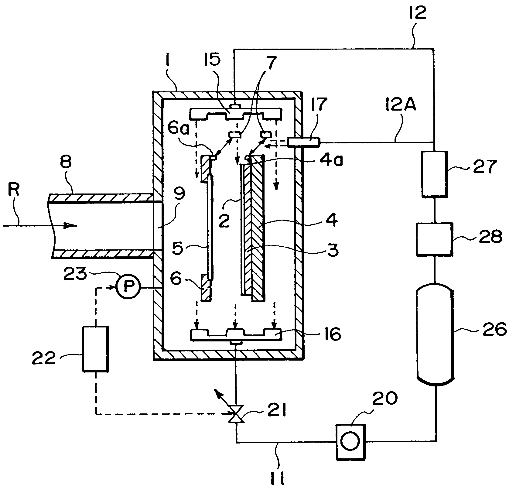
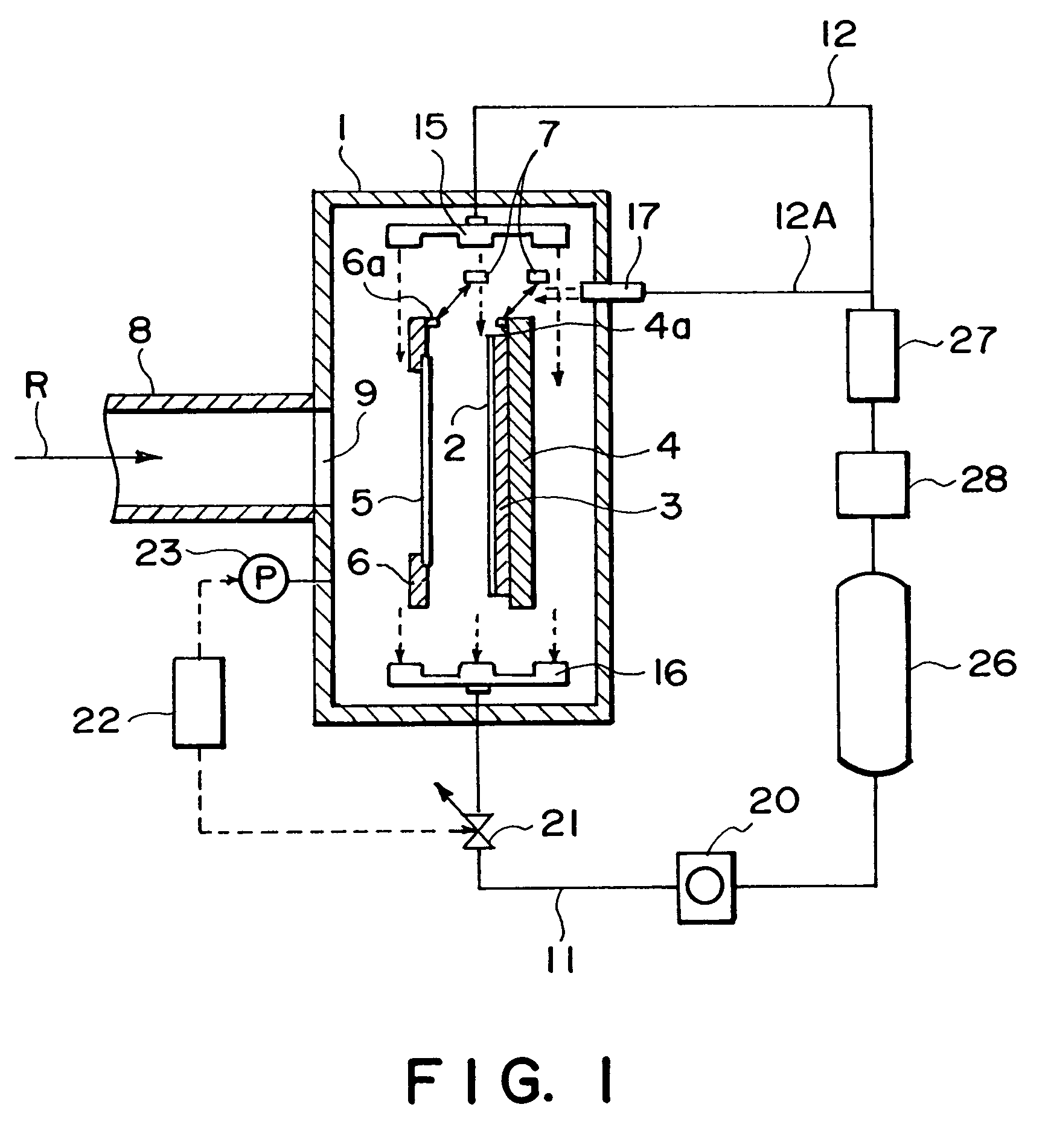
[0137]Referring to FIG. 1, an embodiment of the present invention will be described. FIG. 1 is a schematic view of an embodiment of the present invention in the form of a processing apparatus, that is, a semiconductor exposing apparatus.

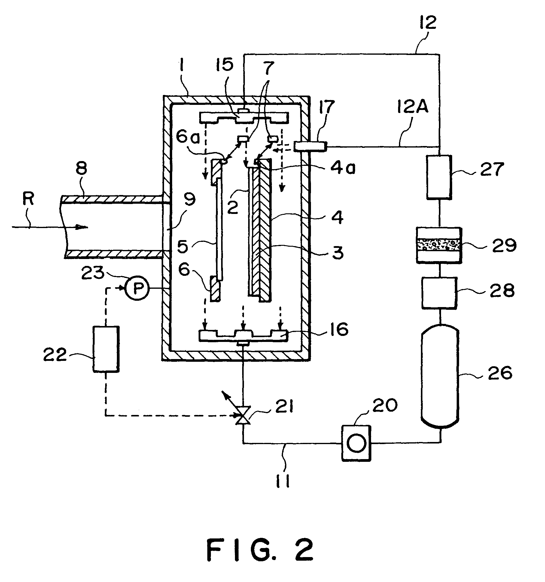
[0138]A referential character 4 designates a positioning stage equipped with a suction chuck 3. The positioning stage 4 is placed in a sealed vacuum container 1 (hereinafter, “vacuum chamber”). The suction chuck 3 holds a piece of substrate 2 or wafer, with the use of suction. A referential character 6 designates a mask holding apparatus which holds a mask 5. Designated by a referential character 7 is a laser interferometry based measuring device, which is used to measure the position of the positioning stage 4. The positioning stage 4 which is holding the substrate 2 is accurately positioned based on the results of the me...


PUM

PropertyMeasurementUnit
temperatureaaaaaaaaaa

Abstract

A processing apparatus includes a sealed vacuum chamber which contains a processing portion; a pressure controlling system which keeps the internal pressure of the sealed vacuum chamber constant at a predetermined level by exhausting the ambient gas in the sealed vacuum chamber; and an ambient gas recirculating system which recirculates the ambient gas exhausted from the sealed vacuum chamber back into the sealed vacuum chamber; wherein the ambient as recirculated by the ambient gas recirculating system is blown into the sealed vacuum chamber so that a gas flow is generated in a predetermined direction along the processing portion.

Description

[0001]This application is a division of application Ser. No. 09 / 257,258, filed Feb. 25, 1999 now U.S. Pat. No. 6,616,898.BACKGROUND OF THE INVENTIONField of the Invention and Related Art[0002]The present invention relates to a processing apparatus equipped with a sealed vacuum device which contains a processing portion. In particular, it relates to a processing apparatus suitable for the manufacture of a semiconductor element, or the like. It also relates to a device manufacturing method which employs such a processing apparatus.[0003]In the manufacture of a semiconductor element or the like, an exposing apparatus is used. As semiconductor elements have been rendered microscopic and highly integrated, X-ray has come to attract attention as one of the most promising choices of exposing light. The rate of the X-ray attenuation caused by the presence of the atmospheric air is extremely high. Therefore, when an X-ray is used as the exposure beam for a semiconductor exposing apparatus, t...

Claims


Application Information

Patent Timeline
Patent Type & Authority Patents(United States)
IPC IPC(8): G05B1/00G05B23/00G03F7/20H01L21/027G05D16/00G05D16/20
CPCG05D16/2013
Inventor HARA, SHINICHITANAKA, YUTAKATERASHIMA, SHIGERUHASEGAWA, TAKAYUKIMATSUI, SHIN
Owner CANON KK
Why Eureka
Try Eureka