Sensor utilizing attenuated total reflection

a total reflection and sensor technology, applied in the direction of phase-affecting property measurement, instruments, measurement devices, etc., can solve the problems of inability to accurately measure the refractive index distribution and the two-dimensional sensor, and achieve the effect of eliminating coherent noise, accurate measurement, and high degree of accuracy

Inactive Publication Date: 2006-01-31
FUJIFILM HLDG CORP +1
View PDF5 Cites 14 Cited by
  • Summary
  • Abstract
  • Description
  • Claims
  • Application Information

AI Technical Summary

Benefits of technology

[0020]The present invention has been made in view of the circumstances mentioned above. Accordingly, it is an object of the present invention to provide a planar type sensor, utilizing ATR, which is capable of measuring the refractive index distribution of a sample with a high degree of accuracy, while eliminating image distortion due to totally reflected light. Another object of the present invention is to provide a sensor, utilizing ATR, which is capable of making an accurate measurement, even when making a laser light beam strike an interface as a parallel light beam having a cross section of considerable size and then detecting the reflected light beam.
[0028]The sensor of the present invention utilizing ATR is provided with an optical compensation system for compensating for image distortion that occurs when the incidence angle of a light beam with respect to the interface between the dielectric block and the thin film layer varies. With this compensation system, image distortion is eliminated and the refractive index distribution of a sample can be measured with a high degree of accuracy.
[0029]To prevent a reduction in accuracy of measurement due to coherent noise and in accordance with the present invention, there is provided a fourth sensor utilizing attenuated total reflection, which comprises a light source for emitting a light beam; a measuring unit comprising (1) a dielectric block transparent to the light beam, (2) a thin film layer formed on a first face of the dielectric block, and (3) a sample holding mechanism for holing a sample on the thin film layer; an optical incidence system for collimating the light beam so that the light beam has a cross section of considerable size, and making the collimated light beam enter the dielectric block at a predetermined incidence angle so that a condition for total internal reflection is satisfied at an interface between the dielectric block and the thin film layer; a screen, disposed in an optical path of the collimated light beam totally reflected at the interface, for converting light intensity distribution in the cross section of the collimated light beam into a visual image; a two-dimensional sensor on which the visual image on the screen is formed; and an optical image-forming system for forming the visual image on the screen onto the two-dimensional sensor.
[0038]In the aforementioned sensors of the present invention utilizing ATR, a collimated light beam with a cross section of considerable size strikes the interface. An image carried by the light beam reflected at the interface is visually formed onto a screen and is diffused. After diffusion, the image is formed onto a two-dimensional sensor. Because of this, the present invention is capable of eliminating coherent noise that occurs when a laser light beam is employed, and making an accurate measurement. Thus, the present invention is capable of making a measurement of the two-dimensional physical property information of a sample and a simultaneous measurement of samples with a high degree of accuracy.
[0039]In the case where a sensing medium that interacts with a specific component in a sample is disposed on a thin film layer, and the sample holding mechanism is provided with a passage through which a liquid sample passes while contacting the sensing medium, the density of the sample can be kept constant even when the specific component gradually reacts with the sensing medium, because the liquid sample is passing through the passage during measurement. In addition, if a plurality of sensing media are disposed on different positions on the thin film layer, different specific substances in the sample that interact with the sensing media can be simultaneously detected and measurement efficiency can be enhanced.

Problems solved by technology

However, in the conventional sensor utilizing ATR, which is constructed to detect the refractive index distribution of a sample in the aforementioned manner, there are cases where the image by totally reflected light is distorted and therefore the refractive index distribution cannot be accurately measured.
On the other hand, in the sensor utilizing ATR, in which a parallel light beam is caused to strike an interface to detect the light intensity distribution of the cross section of reflected light, there are cases where a laser light is employed and, because of this, the light intensity distribution of a light beam detected by photodetection means (two-dimensional sensor) cannot be accurately measured due to coherent noise caused by the laser light beam.
Particularly, in the case of a charge-coupled device (CCD) sensor being employed as a two-dimensional image sensor, there are cases where multiple interferences due to coherent noise take place within a protective film usually provided on the light-receiving face of the CCD sensor and therefore interference stripes occur on an image plane.
Thus, there is a great influence due to coherent noise.

Method used


Image

  • Sensor utilizing attenuated total reflection
  • Sensor utilizing attenuated total reflection
  • Sensor utilizing attenuated total reflection

Examples


first embodiment

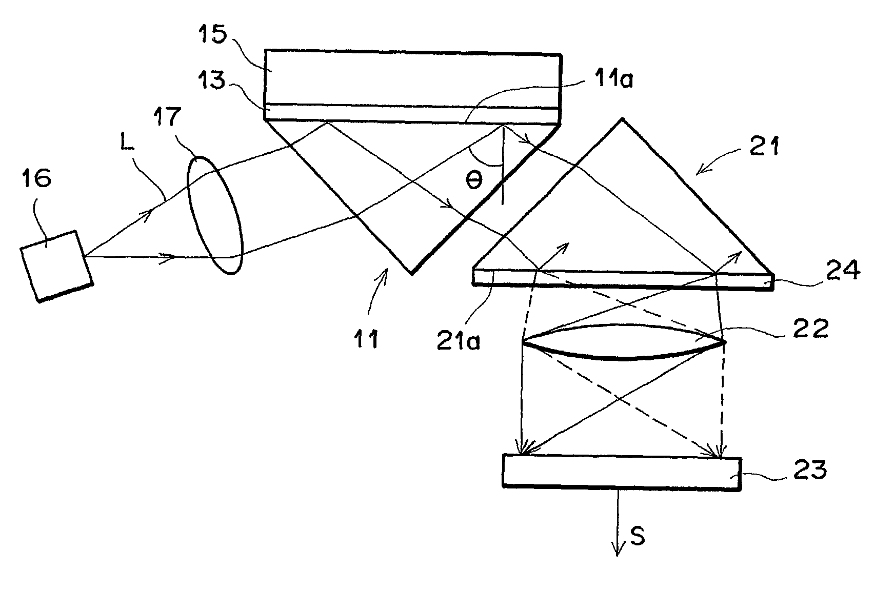
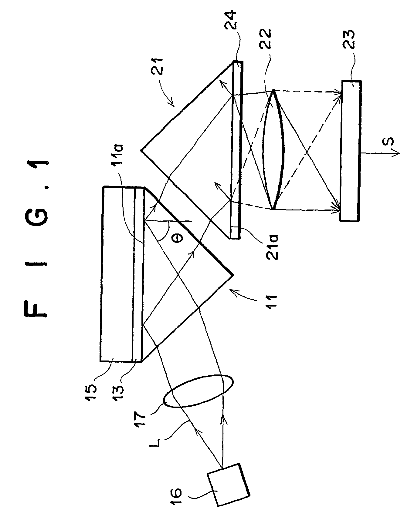
[0052]Referring now in greater detail to the drawings and initially to FIG. 1, there is shown a sensor utilizing ATR, in accordance with the present invention.

[0053]The sensor of the first embodiment is formed as the aforementioned surface plasmon resonance sensor. As shown in FIG. 1, the sensor has a transparent dielectric block 11 and a metal film 13. The dielectric block 11 is formed from synthetic resin such as polymethylmethacrylate (PMMA), etc., or optical glass such as BK7, etc., and is formed, for example, into the shape of a trigonal prism. The metal film 13 is formed, for example, from gold, silver, copper, aluminum, etc., and is mounted on the top face of the dielectric block 11. A sample 15 to be analyzed is disposed on the metal film 13.

[0054]The sensor is further provided with a laser light source 16 for emitting a light beam L; a collimator lens 17 for collimating the light beam L emitted divergently from the laser light source 16; a compensating prism 21 for compensa...

second embodiment

[0064]FIG. 3 shows the present invention utilizing ATR. Note in the figure that the same reference numerals are applied to the same parts as those in FIG. 1, and that a description thereof will not be given unless particularly necessary (the same applies to all of the following descriptions).

[0065]The second embodiment utilizing ATR is also formed as the aforementioned surface plasmon resonance sensor. The sensor of the second embodiment differs from the sensor shown in FIG. 1 in that a sensing medium 14 is mounted on a first dielectric prism 11 and that a sample 15 to be analyzed is placed on the sensing medium 14. The remaining points are constructed the same way as the sensor of FIG. 1.

[0066]The sensing medium 14 couples with a specific substance in the sample 15. As a combination of the specific substance and the sensing medium 14, there is, for example, a combination of an antigen and an antibody.

[0067]In the second embodiment, the refractive index of the sensing medium 14 vari...

fourth embodiment

[0073]The fourth embodiment is further provided with a second dielectric block 70 for image distortion compensation, and a second dielectric plate 71 joined with the bottom face of the second dielectric block 70 through refractive index-matching oil 72. A bottom face 71a (which is a face corresponding to the face of the first dielectric plate 61 constituting the interface 61a) of the second dielectric plate 71 is provided with a diffusing film 24.


PUM

PropertyMeasurementUnit
thicknessaaaaaaaaaa
thicknessaaaaaaaaaa
attenuated total reflectionaaaaaaaaaa

Abstract

Disclosed herein is a sensor utilizing attenuated total reflection. The sensor includes a first dielectric block; a thin film layer, formed on a first face of the dielectric block, for placing a sample thereon; and a light source for emitting a light beam. The sensor further includes an optical incidence system for collimating the light beam, and making the collimated light beam enter the dielectric block at a predetermined incidence angle so that a condition for total internal reflection is satisfied at an interface between the dielectric block and the thin film layer; a photodetector for detecting the refractive index distribution of the sample obtained within a plane along the interface, by detecting an image carried by the light beam totally reflected at the interface; and an optical compensation system for compensating for image distortion produced by the dielectric block when the predetermined incidence angle of the light beam varies.

Description

BACKGROUND OF THE INVENTION[0001]1. Field of the Invention[0002]The present invention relates to a sensor utilizing attenuated total reflection (hereinafter referred to as ATR), such as a surface plasmon resonance sensor that detects the refractive index of a sample by utilizing the generation of surface plasmon, and more particularly to a sensor, utilizing ATR, which detects the refractive index distribution of a sample and a sensor, utilizing ATR, which detects a two-dimensional measuring region with a parallel light beam.[0003]2. Description of the Related Art[0004]In metals, if free electrons are caused to vibrate in a group, compression waves called plasma waves will be generated. The compression waves generated in a metal surface are quantized and called surface plasmon.[0005]A wide variety of surface plasmon resonance sensors have been proposed to quantitatively analyze a substance in a sample by taking advantage of a phenomenon that surface plasmon is excited by light waves....

Claims


Application Information

Patent Timeline
Patent Type & Authority Patents(United States)
IPC IPC(8): G01N21/55
CPCG01N21/553
Inventor NAYA, MASAYUKI
Owner FUJIFILM HLDG CORP
Why Eureka
Try Eureka