
Toughness enhanced silicon-containing composite bodies, and methods for making same

a composite body and enhanced technology, applied in the field of toughened siliconceramic composite bodies, can solve the problems of low fracture toughness, difficult to produce with a low toughness ceramic, and not suitable for many applications

Inactive Publication Date: 2006-02-07
BUSINESS ALLIANCE CAPITAL +1
View PDF17 Cites 38 Cited by
  • Summary
  • Abstract
  • Description
  • Claims
  • Application Information

AI Technical Summary

Benefits of technology

[0020]It is an object of the instant invention to produce a composite material that is lightweight, stiff, strong and substantially pore-free.
[0022]It is an object of the instant invention to produce a silicon-containing composite material of enhanced toughness.
[0023]It is an object of the instant invention to produce a toughened silicon-containing composite material without requiring complex reinforcement debonding / pull-out mechanisms.
[0026]This toughening effect has been observed in certain reaction-bonded boron carbide composites (RBBC). In this system, a molten infiltrant containing silicon and one or more sources of boron is contacted to a porous mass that contains at least some boron carbide, and also containing at least some free carbon. The molten infiltrant infiltrates the porous mass without a pressure or vacuum assist to form a composite body of near theoretical density. The silicon component of the infiltrant reacts with the free carbon in the porous mass to form in-situ silicon carbide as a matrix phase. Further, the tendency of the molten silicon to react with the boron carbide component can be suppressed or at least greatly attenuated by the alloying or doping of the silicon with the boron source. The resulting composite body thus comprises boron carbide dispersed or distributed throughout the silicon carbide matrix. Typically, some residual, unreacted infiltrant phase containing silicon and boron is also present and similarly distributed or interspersed throughout the matrix.

Problems solved by technology

However, they typically also exhibit low fracture toughness, and are therefore not suited for many applications where impact loading will occur.
In addition, the composite can be used in thin walled component designs that would be difficult to produce with a low toughness ceramic.
Although they desire a certain amount of reaction of the boron carbide phase, they also recognize that excessive reaction often causes cracking of the body, and they accordingly recognize that excessive processing temperatures and excessively fine-grained boron carbide is harmful in this regard.
At the same time, they also realize that excessively large-sized grains reduce strength and degrade ballistic performance.
Moreover, many armor applications such as aircraft and body armor, require low mass.
None of the individual components of this reaction bonded boron carbide system possesses inherent toughness.

Method used


Image

  • Toughness enhanced silicon-containing composite bodies, and methods for making same
  • Toughness enhanced silicon-containing composite bodies, and methods for making same
  • Toughness enhanced silicon-containing composite bodies, and methods for making same

Examples


example 1

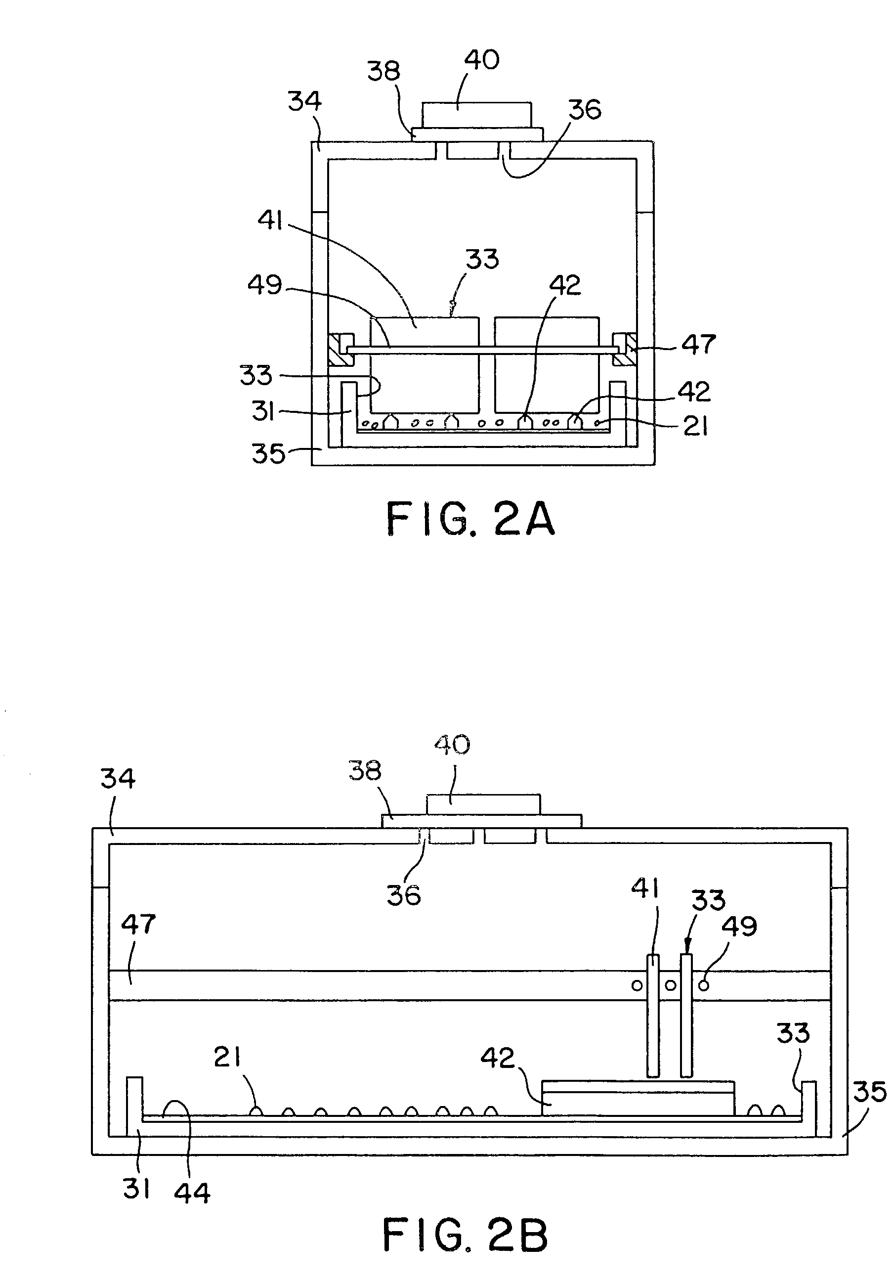
[0072]This example demonstrates the production via reactive infiltration of a Si / SiC composite body containing a boron carbide reinforcement, i.e., “RBBC”. More specifically, this Example demonstrates the infiltration of a silicon-containing melt into a preform containing an interconnected carbon phase derived from a resinous precursor, and silicon carbide and boron carbide particulates.

[0073]Preforms were prepared by a sedimentation casting process. Specifically, about 28 parts of water were added to 100 parts of ceramic particulate and 8 parts of KRYSTAR 300 crystalline fructose (A. E. Staley Manufacturing Co.) to make a slurry. The ceramic particulate content consisted of about equal weight fractions of 220 grit TETRABOR® boron carbide (ESK GmbH, Kempten, Germany, distributed by MicroAbrasives Corp., Westfield, Mass.) having a median particle size of about 66 microns and 500 grit CRYSTOLON green silicon carbide (St. Gobain / Norton Industrial Ceramics) having a median particle size...

example 2

[0086]The technique of Example 1 was substantially repeated, except that no silicon carbide particulate was used in fabricating the preform, and the particle size distribution of the boron carbide was modified such that substantially all particles were smaller than about 45 microns. Following the pyrolysis step, the preforms contained about 75 percent by volume of the boron carbide particulate and about 4 percent by volume of carbon.

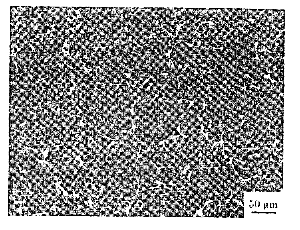
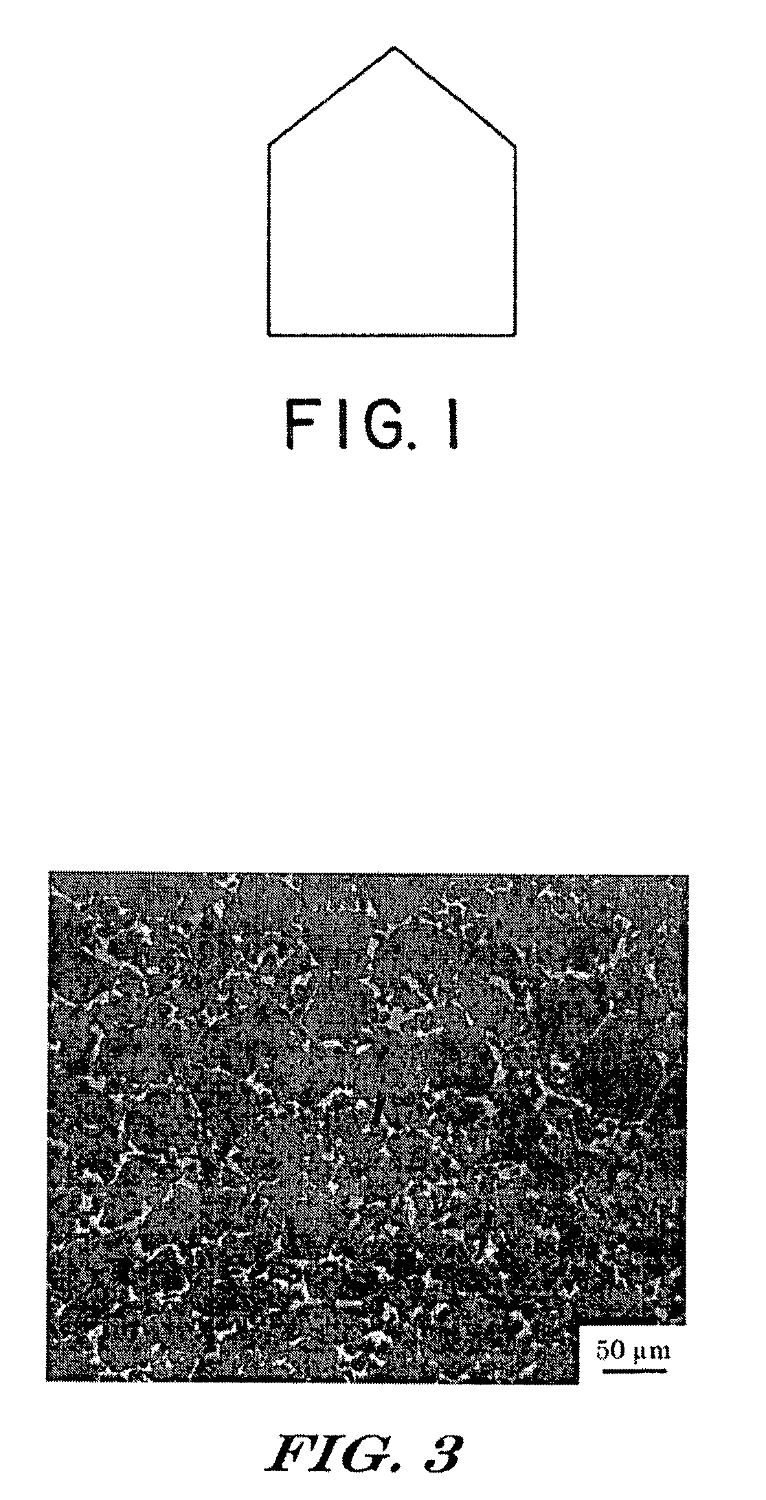
[0087]After infiltration, the ceramic material contained nominally 75 vol. % boron carbide, 9 vol. % reaction-formed SiC, and 16 vol. % remaining Si (i.e., an RBBC composite). A polished section was examined using a Nikon Microphot-FX optical microscope. An optical photomicrograph of the material is shown in FIG. 3. It is clearly evident that, by careful selection of processing conditions, including addition of a source of boron to the silicon infiltrant, little growth and interlocking of the particles has occurred, thus allowing a relatively fine micros...

example 3

[0088]The technique of Example 2 was substantially repeated, except that, before supplying the silicon infiltrant to the lay-up, a monolayer of TETRABOR® boron carbide particulate (220 grit, ESK) was sprinkled onto the carbon cloth between the feeder rails. The amount of silicon was concomitantly increased to account for the added boron carbide, and to maintain an excess supply of silicon of about 10 percent, as in Example 1.


PUM

PropertyMeasurementUnit
diameteraaaaaaaaaa
temperatureaaaaaaaaaa

Abstract

A silicon-containing composite body that would otherwise be brittle can be engineered to exhibit enhanced fracture toughness. Specifically, a silicon-ceramic composite body is produced, preferably by a reactive infiltration technique. The ceramic is selected such that it has a higher coefficient of thermal expansion (CTE) than does the silicon phase. At least at some point during processing, the silicon phase is at a temperature above its normal ductile / brittle transition temperature of about 500° C., and preferably above its melting point. The formed composite body containing the silicon phase is then cooled below its ductile / brittle transition. During cooling, the ceramic phase shrinks more than does the silicon phase, thereby placing the latter in a state of compressive stress. By the time the composite body has cooled to substantially ambient temperature, the induced compressive stress in the silicon phase is sufficient as to impart a measurable degree of semi-ductile character to the silicon phase. This pseudo-ductility manifests itself in the composite body as a significant increase in the fracture toughness of the body. For example, when the ceramic reinforcement was boron carbide particulate instead of silicon carbide (which has a CTE similar to that of silicon), fracture toughness increased by almost 30 percent.

Description

[0001]This patent document is a Continuation-in-Part of U.S. patent application Ser. No. 09 / 990,175, now U.S. Pat. No. 6,862,970 filed on Nov. 20, 2001, which application claims the benefit of U.S. provisional patent application Ser. Nos. 60 / 329,358, and 60 / 252,489, filed on Oct. 15, 2001, and Nov. 21, 2000, respectively.BACKGROUND OF THE INVENTION[0002]1. Field of the Invention[0003]This invention relates to toughened silicon-ceramic composite bodies, especially those produced by a reactive infiltration process, e.g., reaction-bonded bodies. Reaction-bonded silicon carbide having a boron carbide filler or reinforcement particularly exemplifies the invention.[0004]2. Discussion of Related Art[0005]Reaction bonded silicon carbide (SiC) ceramics combine the advantageous properties of high performance traditional ceramics, with the cost effectiveness of net shape processing. These materials provide high surface hardness, very high specific stiffness, high thermal conductivity, and very...

Claims


Application Information

Patent Timeline
Patent Type & Authority Patents(United States)
IPC IPC(8): C04B35/577C04B35/573F41H5/00C04B35/563F41H5/04
CPCF41H5/0435C04B35/565C04B35/573C04B35/6261C04B35/62625C04B35/62655F41H5/0414C04B35/563B32B2315/02C04B2235/3821C04B2235/3826C04B2235/405C04B2235/422C04B2235/428C04B2235/48C04B2235/5248C04B2235/5436C04B2235/5472C04B2235/728C04B2235/77C04B2235/80C04B2235/94C04B2235/96C04B2237/365
Inventor AGHAJANIAN, MICHAEL K.
Owner BUSINESS ALLIANCE CAPITAL
Learn More