Projection optical system, exposure apparatus, and device manufacturing method
- Summary
- Abstract
- Description
- Claims
- Application Information
AI Technical Summary
Benefits of technology
Problems solved by technology
Method used
Image
Examples
first embodiment
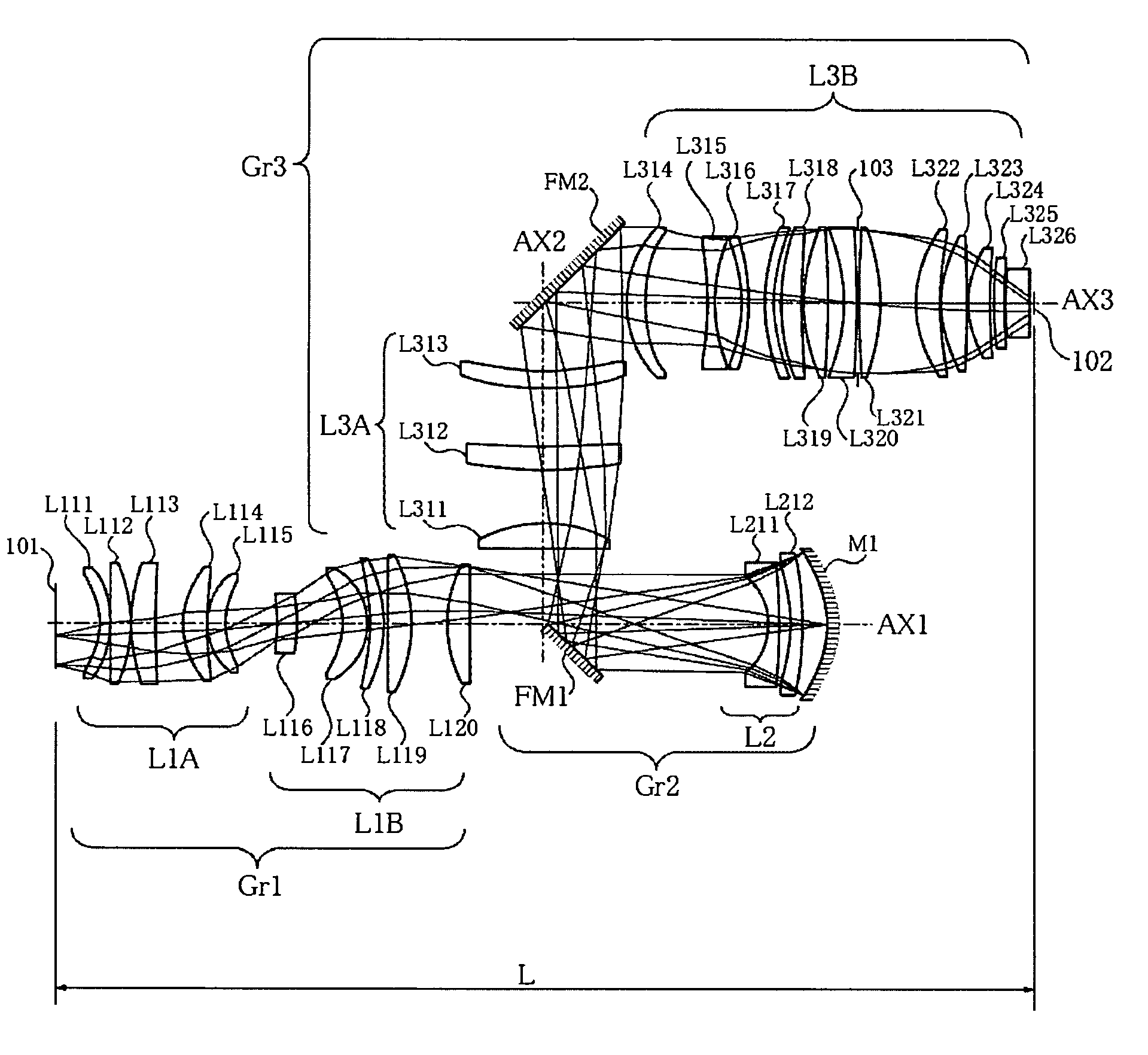
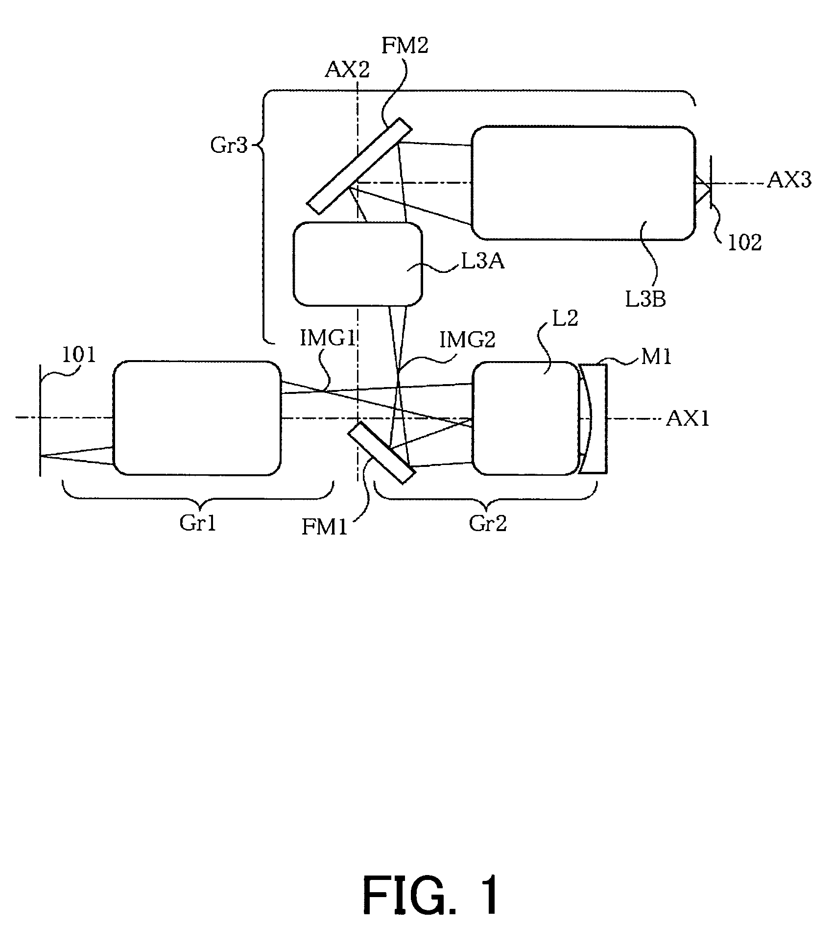
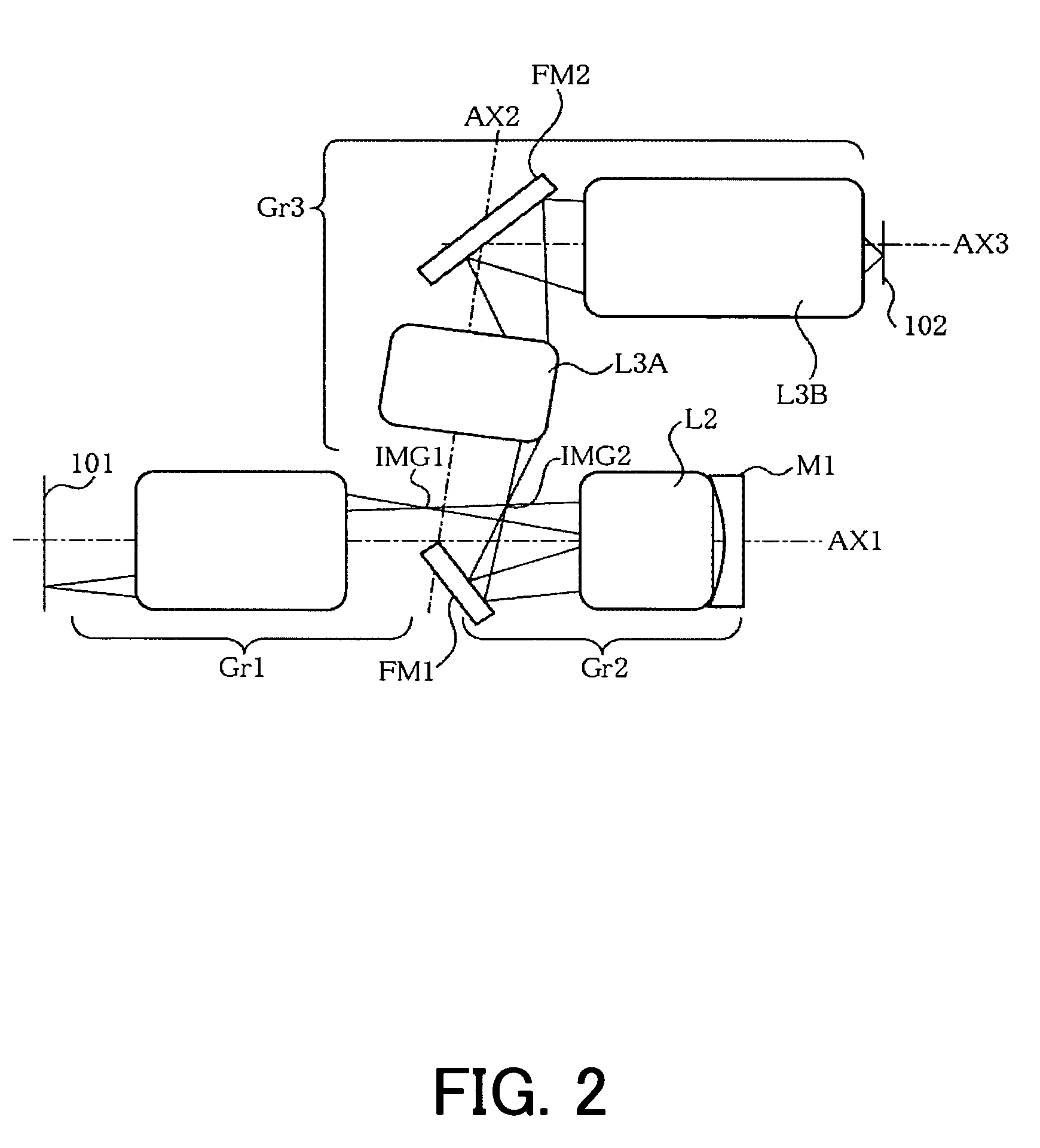
[0086]FIG. 3 shows a specific structure of a projection optical system of a first embodiment according to the present invention. This projection optical system projects a pattern on a first object (original picture having a pattern drawn on a reticle, mask, etc.) onto a second object surface, and includes first, second and third imaging optical systems. Although the first embodiment relates to a projection optical system, the present invention is not limited to this application but is applicable to optical equipments having the instant projection optical system, and an exposure apparatus. It also applies to a device fabrication method that uses an exposure apparatus which includes a projection optical system according to the instant embodiment.
[0087]The first imaging optical system shown in FIG. 3 includes, in order from the first object side, a dioptric lens group L1A having a positive refractive power and a dioptric lens group L1B having a positive refractive power. The lens group...
second embodiment
[0099]FIG. 4 shows a specific lens configuration. The first imaging optical system includes, in order from the first object side, a dioptric lens group L1A having a positive refractive power and a dioptric lens group L1B having a positive refractive power. The dioptric lens group L1A having a positive refractive power includes, along a direction of light traveling from the side of the first object 101, a meniscus negative lens L111 with its concave surface oriented toward the first object, an approximately planoconvex aspheric positive lens L112 with its approximately flat surface oriented toward the first object, an approximately planoconvex positive lens L113 with its convex surface oriented toward the first object, a biconvex positive lens L114, and a meniscus positive lens L115 with its convex surface oriented toward the first object. The lens group L1B having a positive power includes a meniscus aspheric negative lens L116 with its concave surface oriented toward the first obje...
third embodiment
[0137]FIG. 12 shows a specific lens configuration of a third embodiment. A first imaging optical system in the figure includes, in order from the first object side, a dioptric lens group L1A having a positive refractive power and a dioptric lens group L1B having a positive refractive power. The dioptric lens group L1A having a positive refractive power includes, along a direction of light traveling from the side of the first object 101, a meniscus negative lens L111 with its concave surface oriented toward the first object side, an approximately planoconvex aspheric positive lens L112 with its convex surface oriented toward the first object side, an approximately planoconvex positive lens L113 with its convex surface oriented toward the first object side, a meniscus positive lens L114 with its convex surface oriented toward the second object side, and a meniscus positive lens L115 with its convex surface oriented toward the first object side. The dioptric lens group L1B having a pos...
PUM
 Abstract
Description
Claims
Application Information
 - R&D
- Intellectual Property
- Life Sciences
- Materials
- Tech Scout
- Unparalleled Data Quality
- Higher Quality Content
- 60% Fewer Hallucinations
Browse by: Latest US Patents, China's latest patents, Technical Efficacy Thesaurus, Application Domain, Technology Topic, Popular Technical Reports.
© 2025 PatSnap. All rights reserved.Legal|Privacy policy|Modern Slavery Act Transparency Statement|Sitemap|About US| Contact US: help@patsnap.com


