Organometallic complexes as phosphorescent emitters in organic LEDs

a technology of organic leds and complexes, applied in the field of organic light emitting devices (oleds), can solve the problems of wasting energy in the triplet state, slow and inefficient luminescence, and few other problems, and achieve the effect of facilitating the combination of l

Inactive Publication Date: 2006-02-21
THE TRUSTEES FOR PRINCETON UNIV +1
View PDF75 Cites 228 Cited by
  • Summary
  • Abstract
  • Description
  • Claims
  • Application Information

AI Technical Summary

Benefits of technology

[0054]The synthetic process of the present invention facilitates the combination of L and X pairs of certain desirable characteristics. For example, the present invention is further directed to the appropriate selection of L and X to allow color tuning of the complex L2MX relative to L3M. For example, Ir(ppy)3 and (ppy)2Ir(acac) both give strong green emission with a λmax of 510 nm (ppy denotes phenyl pyridine). However, if the X ligand is formed from picolinic acid instead of from acetylacetone, there is a small blue shift of about 15 nm.
[0055]Furthermore, the present invention is also directed to a selection of X such that it has a certain HOMO level relative to the L3M complex so that carriers (holes or electrons) might be trapped on X (or on L) without a deterioration of emission quality. In this way, carriers (holes or electrons) which might otherwise contribute to deleterious oxidation or reduction of the phosphor would be impeded. The carrier that is remotely trapped could readily recombine with the opposite carrier either intramolecularly or with the carrier from an adjacent molecule.

Problems solved by technology

For example, if the symmetry of an exciton is different from that of the ground state, then the radiative relaxation of the exciton is disallowed and luminescence will be slow and inefficient.
However, only a very few have been identified which are also capable of efficient room temperature phosphorescence from triplets.
Thus, in most fluorescent dyes, the energy contained in the triplet states is wasted.
This typically restricts the Förster mechanism to transfers between singlet states.
Unfortunately, such systems are affected by competitive energy transfer mechanisms that degrade the overall efficiency.
Once excitons reach the guest triplet state, they are effectively lost since these fluorescent dyes typically exhibit extremely inefficient phosphorescence.
There are issues with the use of phosphorescence.
It may be that long phosphorescent lifetimes cause saturation of emissive sites, and triplet-triplet annihilation may produce efficiency losses.
Another issue is that triplet diffusion lengths are typically long (e.g., >1400 Å) compared with typical singlet diffusion lengths of about 200 Å. Thus, if phosphorescent devices are to achieve their potential, device structures need to be optimized for triplet properties.
Fluorescence is in principle 75% less efficient due to the three times higher number of symmetric excited states.

Method used


Image

  • Organometallic complexes as phosphorescent emitters in organic LEDs
  • Organometallic complexes as phosphorescent emitters in organic LEDs
  • Organometallic complexes as phosphorescent emitters in organic LEDs

Examples


example 1

ITO / PVK:PBD.Pt(thpy)2 (100:40:2) / Ag:Mg / Ag

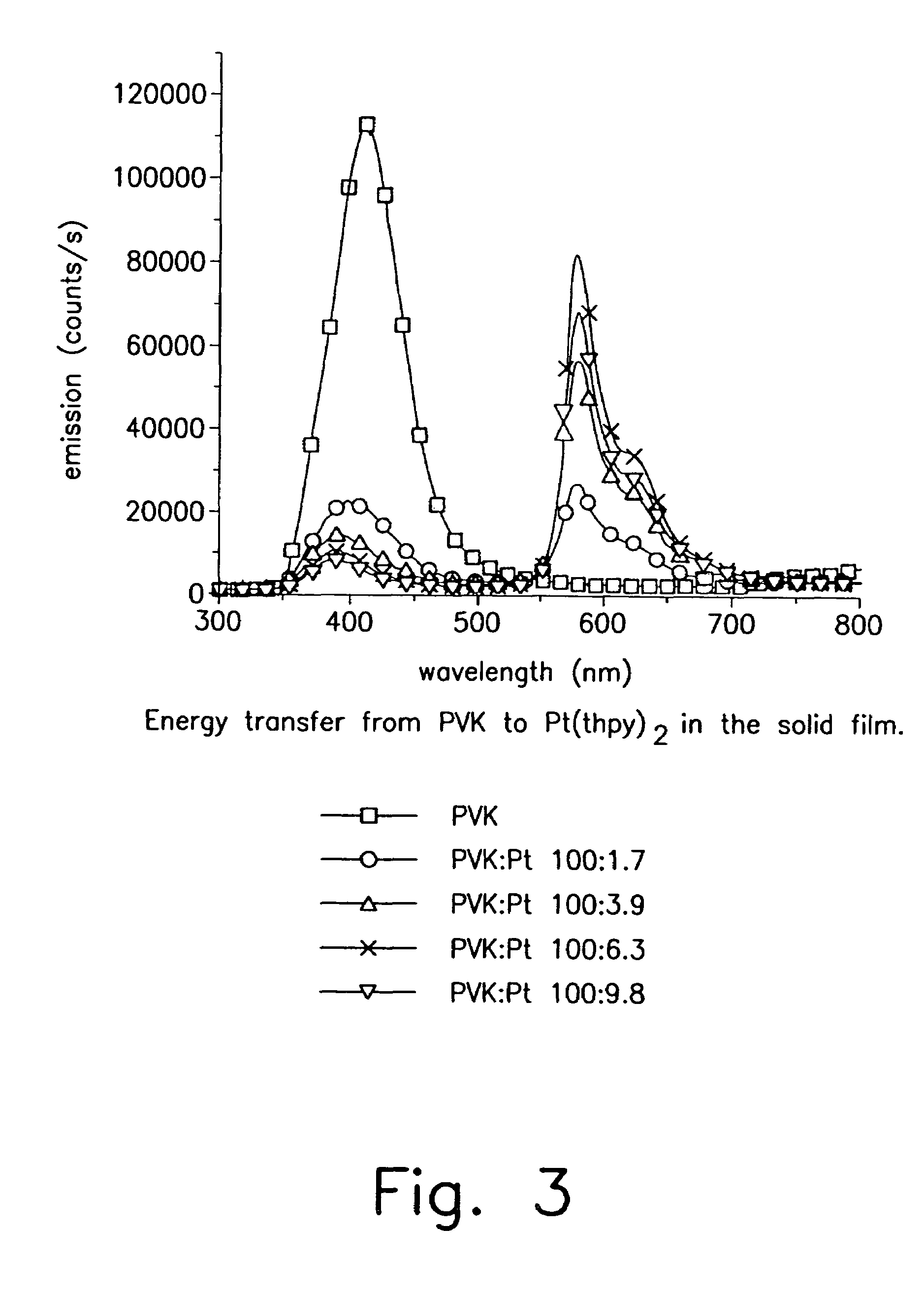
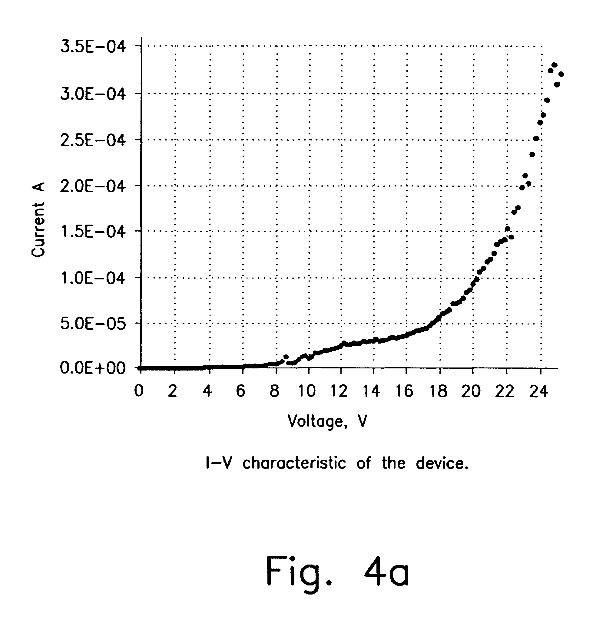
[0147]Pt(thpy)2 does not appear to be stable toward sublimation. In order to test it in an OLED we have fabricated a polymer blended OLED with Pt(thpy)2 dopant. The optimal doping level was determined by the photoluminescence study described above. The emission from this device comes exclusively from the Pt(thpy)2 dopant. Typical current-voltage characteristic and light output curve of the device are shown in FIG. 4. Quantum efficiency dependence on applied voltage is demonstrated in FIG. 5. Thus, at 22 V quantum efficiency is ca. 0.11%. The high voltage required to drive this device is a result of the polymer blend OLED structure and not the dopant. Similar device properties were observed for a polymer blend device made with a coumarin dopant in place of Pt(thpy)2. In addition, electroluminescence spectrum and CIE diagram are shown in FIG. 6.

example 2

[0148]In this example, we describe OLEDs employing the green, electrophosphorescent material fac tris(2-phenylpyridine)iridium (Ir(ppy)3). This compound has the following formulaic representation:

[0149]The coincidence of a short triplet lifetime and reasonable photoluminescent efficiency allows Ir(ppy)3-based OLEDs to achieve peak quantum and power efficiencies of 8.0% (28 cd / A) and ˜30 lm / W respectively. At an applied bias of 4.3V, the luminance reaches 100 cd / m2 and the quantum and power efficiencies are 7.5% (26 cd / A) and 19 lm / W, respectively.

[0150]Organic layers were deposited by high vacuum (10−6 Torr) thermal evaporation onto a cleaned glass substrate precoated with transparent, conductive indium tin oxide. A 400 A thick layer of 4,4′-bis(N-(1-naphthyl)-N-phenyl-amino)biphenyl (α-NPD) is used to transport holes to the luminescent layer consisting of Ir(ppy)3 in CBP. A 200 A thick layer of the electron transport material tris-(8-hydroxyquinoline)aluminum (Alq3) is used to tra...

example 3

[0152]In addition to the doped device, we fabricated a heterostructure where the luminescent region was a homogeneous film of Ir(ppy)3. The reduction in efficiency (to ˜0.8% ) of neat Ir(ppy)3 is reflected in the transient decay, which has a lifetime of only ˜100 ns, and deviates significantly from mono-exponential behavior. A 6% Ir(ppy)3:CBP device without a BCP barrier layer is also shown together with a 6% Ir(ppy)3:Alq3 device with a BCP barrier layer. Here, very low quantum efficiencies are observed to increase with current. This behavior suggests a saturation of nonradiative sites as excitons migrate into the Alq3, either in the luminescent region or adjacent to the cathode.


PUM

PropertyMeasurementUnit
transparencyaaaaaaaaaa
atomic numberaaaaaaaaaa

Abstract

Organic light emitting devices are described wherein the emissive layer comprises a host material containing an emissive molecule, which molecule is adapted to luminesce when a voltage is applied across the heterostructure, and the emissive molecule is selected from the group of phosphorescent organometallic complexes, including cyclometallated platinum, iridium and osmium complexes. The organic light emitting devices optionally contain an exciton blocking layer. Furthermore, improved electroluminescent efficiency in organic light emitting devices is obtained with an emitter layer comprising organometallic complexes of transition metals of formula L2MX, wherein L and X are distinct bidentate ligands. Compounds of this formula can be synthesized more facilely than in previous approaches and synthetic options allow insertion of fluorescent molecules into a phosphorescent complex, ligands to fine tune the color of emission, and ligands to trap carriers.

Description

[0001]This application is a continuation of application Ser. No. 09 / 883,734, filed Jun. 18, 2001, now U.S. Pat. No. 6,830,828, which is a continuation-in-part of application Ser. No. 09 / 274,609, filed Mar. 23, 1999 (now abandoned); application Ser. No. 09 / 452,346, filed Dec. 1, 1999 (now abandoned); and application Ser. No. 09 / 311,126, filed May 13, 1999 (now abandoned). This application is also a division of application Ser. No. 10 / 171,235, filed Jun. 13, 2002, now U.S. Pat. No. 6,902,830, which is a division of application Ser. No. 09 / 883,734, filed Jun. 18, 2001, now U.S. Pat. No. 6,830,828, which is a continuation-in-part of application Ser. No. 09 / 452,346, filed Dec. 1, 1999 (now abandoned).GOVERNMENT RIGHTS[0002]This invention was made with Government support under Contract No. F33615-94-1-1414 awarded by DARPA. The government has certain rights in this invention.FIELD OF INVENTION[0003]The present invention is directed to organic light emitting devices (OLEDs) comprised of em...

Claims


Application Information

Patent Timeline
Patent Type & Authority Patents(United States)
IPC IPC(8): C09K11/06H05B33/14C07D209/86H01L51/00H01L51/30H01L51/50
CPCC07D209/86H01L51/0062H01L51/0067H01L51/0072H01L51/0077H01L51/0085H01L51/0087H01L51/0088H01L51/5016H01L51/5096H05B33/14C09K11/06Y10S428/917C09K2211/1007C09K2211/1014C09K2211/1029C09K2211/1033C09K2211/1037C09K2211/1092C09K2211/185C09K2211/186H01L51/0042H01L51/0059H01L51/006H01L51/0065H01L51/0068H01L51/0071H01L51/0081H01L2251/308H10K85/146H10K85/649H10K85/631H10K85/653H10K85/633H10K85/654H10K85/655H10K85/657H10K85/30H10K85/348H10K85/324H10K85/346H10K85/342H10K85/6572H10K50/11H10K2101/10H10K50/18H10K2102/103C09K2211/188
Inventor THOMPSON, MARK E.DJUROVIC, PETERLAMANSKY, SERGEYMURPHY, DREWKWONG, RAYMONDABDEL-RAZZAQ, FERASFORREST, STEPHEN R.BALDO, MARC A.BURROWS, PAUL E.
Owner THE TRUSTEES FOR PRINCETON UNIV
Why Eureka
Try Eureka