
Planographic printing plate precursor and planographic printing method

a technology of planographic printing plate and precursor, which is applied in thermography, instruments, photosensitive materials, etc., can solve the problems of troublesome handling of exposed printing plate for on-machine development, low strength of formed image portions thereof, and inability to record images with infrared lasers. , to achieve the effect of excellent plate wear resistance and large quantity of good prints

Active Publication Date: 2006-02-28
FUJIFILM CORP
View PDF42 Cites 76 Cited by
  • Summary
  • Abstract
  • Description
  • Claims
  • Application Information

AI Technical Summary

Benefits of technology

[0016]Therefore, an object of the present invention is to provide a negative-type planographic printing plate precursor, on which an image can be directly recorded from digital data from a computer, or the like, by using a solid state laser or a semiconductor laser emitting an infrared ray, which can be made into a printing plate without being wet-type developed, and which does not require heat treatment after exposure to have excellent plate-wear resistance to yield a large quantity of good prints. Another object of the present invention is to provide a planographic printing method using the planographic printing plate precursor which does not require wet-type developing.

Problems solved by technology

However, since an image formed in the photosensitive layer is not fixed until it is developed after exposure in conventional image recording methods, which utilize ultra violet or visible light, handling of the exposed printing plate for on-machine developing is troublesome because the printing plate has to be completely shielded from light and stored at a constant temperature before it is set in a printing machine.
However, since the majority of photosensitive recording materials which are useful in practice have sensitivity to visible light having a wavelength of 760 nm or less, images cannot be recorded on them with an infrared laser.
However, this image recording material has a problem that strength of formed image portions thereof is low, thus if it is used as a planographic printing plate, the number of resulting prints which are acceptable is small.
Although such a method for forming an image by coalescing the fine particles by simple thermal fusing exhibits good on-machine developability, strength of the image is low, and therefore there is a problem of insufficient plate-wear resistance.

Method used


Image

  • Planographic printing plate precursor and planographic printing method
  • Planographic printing plate precursor and planographic printing method
  • Planographic printing plate precursor and planographic printing method

Examples


examples

[0123]Hereinafter, the present invention is described in more detail using examples, however, these examples are not intended to limit the present invention.

examples 1 to 6

Preparation of Substrate

[0124]A melted JIS A1050 alloy comprising 99.5% or more of aluminum, 0.30% of Fe, 0.10% of Si, 0.02% of Ti and 0.013% of Cu was cleaned and then was cast. For the cleaning, degassing for removing unnecessary gas such as hydrogen in the melted alloy and ceramic tube filtering were carried out. The casting was carried out by die-casting. The surface of the solidified ingot thus formed having a thickness of 500 mm was shaved to a depth of 10 mm from the surface, and then, homogenization was carried out for 10 hours at 550° C. so as to prevent bulking of the intermetallic compound. Then, hot-rolling at 400° C. and intermediate annealing at 500° C. for 60 seconds in a continuous annealing furnace were carried out. Thereafter, cold-rolling was carried out to produce a rolled aluminum plate having a thickness of 0.30 mm. The center line average surface roughness Ra after the cold-rolling was controlled to be 0.2 μm by controlling the roughness of the rolling roll. T...


PUM

PropertyMeasurementUnit
Solubility (mass)aaaaaaaaaa
Photosensitivityaaaaaaaaaa
Water absorptionaaaaaaaaaa

Abstract

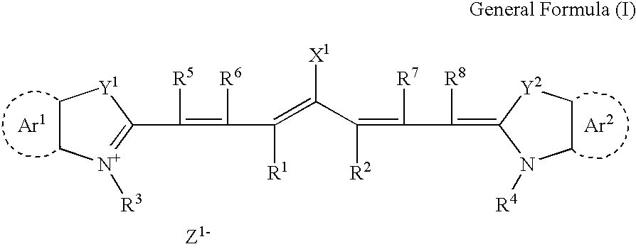
The present invention provides a planographic printing plate precursor comprising a photosensitive layer on a support, the photosensitive layer including an infrared absorbent, a radical polymerization initiator and a radical polymerizing compound, the photosensitive layer being recordable with irradiation with an infrared ray, and being at least one of soluble and dispersible in water.

Description

BACKGROUND OF THE INVENTION[0001]1. Field of the Invention[0002]The present invention relates to a planographic printing plate precursor and a printing method for a planographic printing plate using the same. More particularly, the present invention relates to a planographic printing plate precursor that can be used for direct plate-making by scanning the plate with an infrared laser on the basis of digital signals from a computer, or the like, and to a planographic printing method using the planographic printing plate precursor wherein the printing plate can be developed on a printing machine.[0003]2. Description of the Related Art[0004]Generally, a planographic printing plate is formed of lipophilic image portions which receive ink during printing, and hydrophilic non-image portions which receive dampening water.[0005]Planographic printing utilizes a property of water and oil based ink repelling each other, wherein the lipophilic image portions are used as ink receiving areas and ...

Claims


Application Information

Patent Timeline
IPC IPC(8): G03F7/038G03F7/004B41C1/10G03F7/00G03F7/027G03F7/028
CPCB41C1/1008B41C1/1016B41N3/038Y10S430/146B41C2210/24B41C2201/04B41C2210/04B41C2210/06B41C2210/22Y10S430/145
Inventor HOSHI, SATOSHIAOSHIMA, KEITARO
Owner FUJIFILM CORP
Learn More