Apparatus and methods for launching and receiving a broad wavelength range source

a wavelength range, antenna technology, applied in the direction of optical radiation measurement, lighting and heating apparatus, instruments, etc., can solve the problems of reducing the effect of delay time, reducing the range of sampling delay times, and not being able to use true in-situ probes for monitoring both osub>2 /sub>and co, etc., to enhance the overall robustness of optical beam transport

Inactive Publication Date: 2006-02-28
LAIR LIQUIDE SA POUR LETUDE & LEXPLOITATION DES PROCEDES GEORGES CLAUDE
View PDF10 Cites 22 Cited by
  • Summary
  • Abstract
  • Description
  • Claims
  • Application Information

AI Technical Summary

Benefits of technology

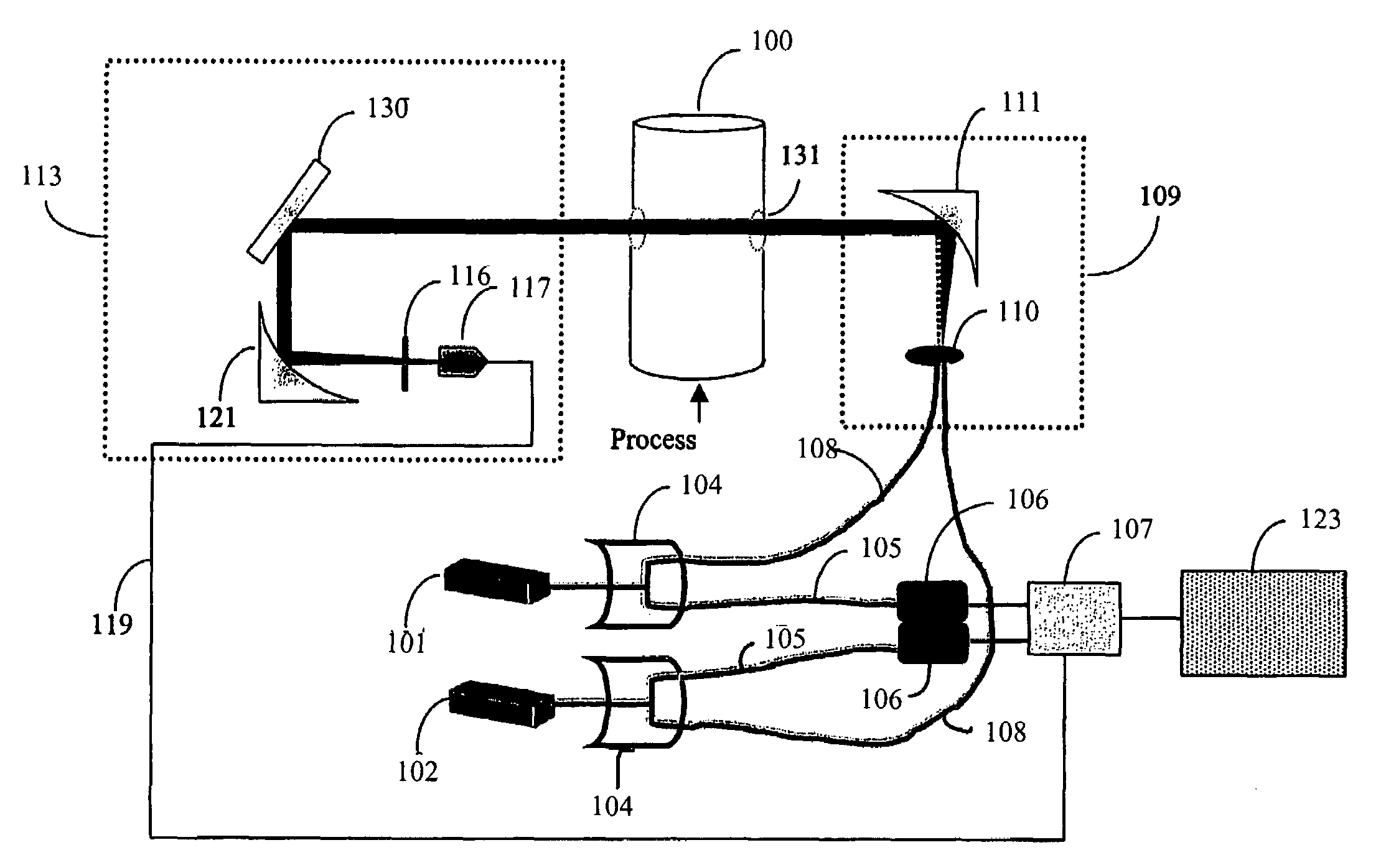
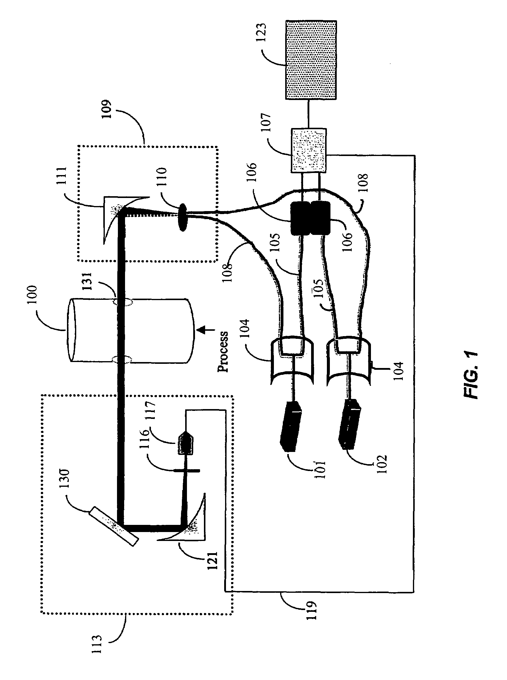
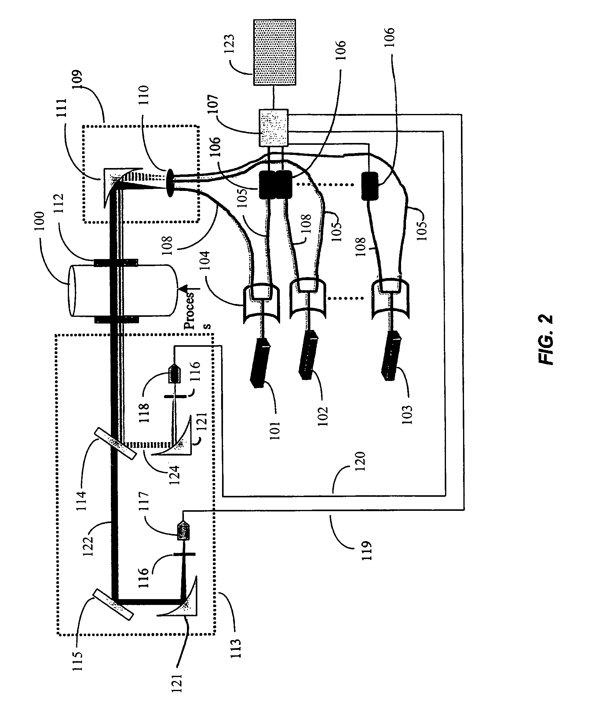
[0015]In accordance with the present invention, launch and receiver designs are described that address the drawbacks outlined above. The innovative designs are adaptable to broad wavelength range sources with minimum number of optical components. The simplicity of the designs enhances overall robustness of the optical beam transport, which is advantageous in industrial applications. The designs presented here are preferably can be divided into separate categories; launch and receiver; and near and far field. A complete description is presented herein.
[0018](b) each of the N laser sources adapted to transmit radiation through an optical fiber (preferably dedicated), each optical fiber having single-mode optical fiber characteristics sufficient to insure single-mode transmission with minimal power loss to a beam splitter, said beam splitter sending a first portion of each of the N laser's radiation to a balanced ratiometric detector, and a second portion to a compound ferrule;
[0025](b) transmitting radiation from each of the N laser sources through an optical fiber (preferably dedicated), each optical fiber having single-mode optical fiber characteristics sufficient to insure single-mode transmission with minimal power loss to a beam splitter, the beam splitter sending a first portion of each of the N laser's radiation to a balanced ratiometric detector, and a second portion to a compound ferrule;
[0032](b) each of the N laser sources adapted to transmit radiation through an optical fiber (preferably dedicated), each optical fiber having single-mode optical fiber characteristics sufficient to insure single-mode transmission with minimal power loss to N achromate lenses, each achromate lens having a proper wavelength-specific anti-reflective coating, the N achromate lens adapted to create N collimated laser beams;
[0035]Preferred apparatus are those wherein the means for receiving and detecting comprises a prism and an achromate lens, and spherical lens combination that provides wavelength dispersion, beam focusing, and spatial control. The wavelength dispersion provides a means to separate the individual N wavelengths launched through the process, while focusing controls the beam spatial position relative to the detection means. Apparatus embodiments within the third aspect of the invention are less sensitive to beam steering effects that can occur due to process vibration, alignment drifting, and refractive index changes due to hot gas environments.

Problems solved by technology

This technology suffers from probe and sample line plugging and other maintenance issues such as corrosion when applied to harsh process environments as encountered in glass melting tanks, steel processing furnaces, chemical processing systems, etc.
In addition to maintenance issues, long sampling lines reaching up to several hundred feet are not uncommon resulting in sampling delay times that can range form seconds to several minutes.
In-situ monitoring of the combustion space reduces the effect of delay time; however, true in-situ probes for monitoring both O2 and CO are not commercially available.
Despite the elimination of the sampling line, response times are still on the order of 10's of seconds and maintenance issues persist on high particle density applications, since the gas is drawn through the instrument.
However, the current tuning range for standard diode lasers, for example, distributed feedback or vertical cavity surface emitting lasers (VCSEL's), are limited to only ˜1–3 cm−1.
The maximum off-the-shelf broadband antireflective coating available can approach ˜500 nm in the NIR over the range of 1050–1600 nm, which is not sufficient for use in an O2 and CO monitoring application.
This approach is both costly and cumbersome, limiting the application to only cases where the additional cost can be justified.
Though the system incorporates a broad wavelength range, issues related to placement of the sensitive lasers and associated electronics near the harsh combustion process and the complexity of the optical arrangement to collimate and combine the beams are significant drawbacks.
For industrial applications, the lack of robustness is not acceptable for continues day-to-day operation.

Method used


Image

  • Apparatus and methods for launching and receiving a broad wavelength range source
  • Apparatus and methods for launching and receiving a broad wavelength range source
  • Apparatus and methods for launching and receiving a broad wavelength range source

Examples


example 1

[0069]Using the receiver module illustrated in FIG. 8, sample sets of data were collected from an industrial 30 MW furnace installation and on a 500 kW pilot furnace. For the industrial furnace, the beam launch system illustrated in FIG. 6 was employed with a 48 foot (14.6 meters) pathlength across the process to the receiver module. In this case, O2 and H2O were detected in the process by scanning a diode laser at 200 Hz over a wavelength range to collect the full lineshape. A detailed description of the monitoring methodology is described in assignee's copending published patent application 20020031737, Ser. No. 09 / 964,017, published Mar. 14, 2002, incorporated herein by reference. The resulting absorbance spectrum for O2 monitoring is illustrated in FIG. 9, with absorbance defined as

A=ε1c

Where A is the absorbance, ε is the absorptivity, 1 is the pathlength, and c is the concentration of the species being monitored. This relationship comes directly out of Beer's Law. The raw data ...

example 2

[0070]An example illustrating simultaneous H2O concentration, gas temperature and CO concentration from a 500 kW pilot furnace is illustrated in FIG. 11, with the raw data listed in Table 4. In this example, the furnace pathlength as only 1 foot (30.5 cm) and no O2 was present. (Note, the spectral region and simultaneous detection of H2O and CO in this region is discussed in assignee's U.S. Provisional Application No. 60 / 349,638, filed Jan. 17, 2002, incorporated herein by reference. In this example, the gas temperature was 1387 K based on the H2O peaks A and B resulting in a CO concentration of 4.7%. In addition, the H2O concentration based on peak A, 36.6% for this example can also be obtained.

[0071]Examples 1 and 2 illustrate the multi-species detection capabilities of the apparatus of the invention under industrial operating conditions where high levels of background radiation are present, strong thermal gradients are present resulting in the beam spatial position changing in ti...


PUM

PropertyMeasurementUnit
timeaaaaaaaaaa
diameteraaaaaaaaaa
diameteraaaaaaaaaa

Abstract

An apparatus and method for simultaneous detection of N gas species through laser radiation attenuation techniques is disclosed. Each of the N species has a spectral absorption band. N laser sources operate at a wavelength λN in a spectral absorption band separated by the cutoff wavelength for single-mode transmission. Each laser source corresponds to a gas species and transmits radiation through an optical fiber constructed and arranged to provide single-mode transmission with minimal power loss.

Description

CROSS-REFERENCE TO RELATED APPLICATIONS[0001]This application is related to abandoned application Ser. No. 09 / 433,667, filed Nov. 4, 1999, and to application Ser. No. 09 / 522,915, filed Mar. 10, 2000 and Ser. No. 60 / 334,273, filed Nov. 30, 2001, all of which are incorporated herein by reference. This application claims the benefit of U.S. Provisional Application No. 60 / 334,273, filed Nov. 30, 2001.STATEMENT REGARDING FEDERALLY FUNDED RESEARCH[0002]The United States Government has a paid-up license in this invention and the right in limited circumstances to require the patent owner to license others on reasonable terms as provided for by the terms of Prime Contract no. DE-FC02-00CH11030 award by the Department of Energy.BACKGROUND OF THE INVENTION[0003]1. Brief Description of the Invention[0004]This invention relates generally to apparatus and methods for monitoring and / or control of industrial processes using diode laser-based sensors, in particular monitoring and / or control of combu...

Claims


Application Information

Patent Timeline
Patent Type & Authority Patents(United States)
IPC IPC(8): G02B6/00F23N5/00G01N21/35
CPCF23N5/00G01N21/3504Y02T50/677F23N5/003Y02T50/60
Inventor VON DRASEK, WILLIAM A.SONNENFROH, DAVIDALLEN, MARK G.STAFFORD-EVANS, JOY
Owner LAIR LIQUIDE SA POUR LETUDE & LEXPLOITATION DES PROCEDES GEORGES CLAUDE
Why Eureka
Try Eureka