Image processing for correcting defects of read image

a technology for reading images and image processing, applied in the field of image processing for correcting defects of read images, can solve the problems of inability to fully examine the on/off sequence of visible light sources and invisible light sources such as infrared sources, and the rise sequence has not been optimized, so as to achieve high-precision dust/scratch reduction functions, stable, and accurate dust/scratch detection.

Inactive Publication Date: 2006-02-28
CANON KK
View PDF14 Cites 18 Cited by
  • Summary
  • Abstract
  • Description
  • Claims
  • Application Information

AI Technical Summary

Benefits of technology

[0025]It is another object of the present invention to correct the difference in optical path length between visible and invisible light images with a simple structure using an optical member.
[0026]It is still another object of the present invention to supply a stable, high-precision dust / scratch reduction function.
[0027]It is still another object of the present invention to stably perform appropriate dust / scratch detection and correction even if a shift occurs between images obtained by a plurality of scanning operations when a document is read to achieve dust / scratch correction.
[0028]It is still another object of the present invention to reduce the influence of a shift from an ideal wavelength characteristic, the influence of the shadow of a film holder, and the like.
[0029]It is still another object of the present invention to achieve a high-speed dust / scratch reduction process without decreasing a dust / scratch reduction effect.

Problems solved by technology

For this reason, a very long time is required to correct such defects.
However, no prior art fully examines the ON / OFF sequences of a visible light source and an invisible light source such as an infrared source.
A rise sequence has not been optimized for a combination between a visible light source which requires a relatively long rise time and an invisible light source which requires a relatively short rise time.
A stable, high-precision dust / scratch reduction function is difficult to supply.
This generates a shift due to a poor operation precision of the scanning unit between an image obtained by invisible light scan reading for detecting dust and scratches and an image obtained by visible light scan reading for acquiring actual image information.
As a result, dust and scratches cannot be satisfactorily reduced.
Furthermore, a document read at a high designated resolution provides large image data, which requires a very long time to detect the positions of dust and scratches on visible light and invisible light images.
Further, only a uniform setting of whether to perform dust / scratch reduction cannot achieve a process suitable for an individual film.
It is therefore difficult to set parameters for properly processing both scratches and dust.
If a dust / scratch portion is to be interpolated by neighboring data within a range much larger than the dust / scratch portion so as to completely correct the dust / scratch portion, detailed data within the range other than the dust / scratch is undesirably lost, making the image look unnatural.
In addition, the dust / scratch reduction range to be corrected should vary depending upon the resolution and is difficult to set the range to a detected dust / scratch portion plus a specific number of pixels surrounding the dust / scratch portion.

Method used


Image

  • Image processing for correcting defects of read image
  • Image processing for correcting defects of read image
  • Image processing for correcting defects of read image

Examples


first embodiment

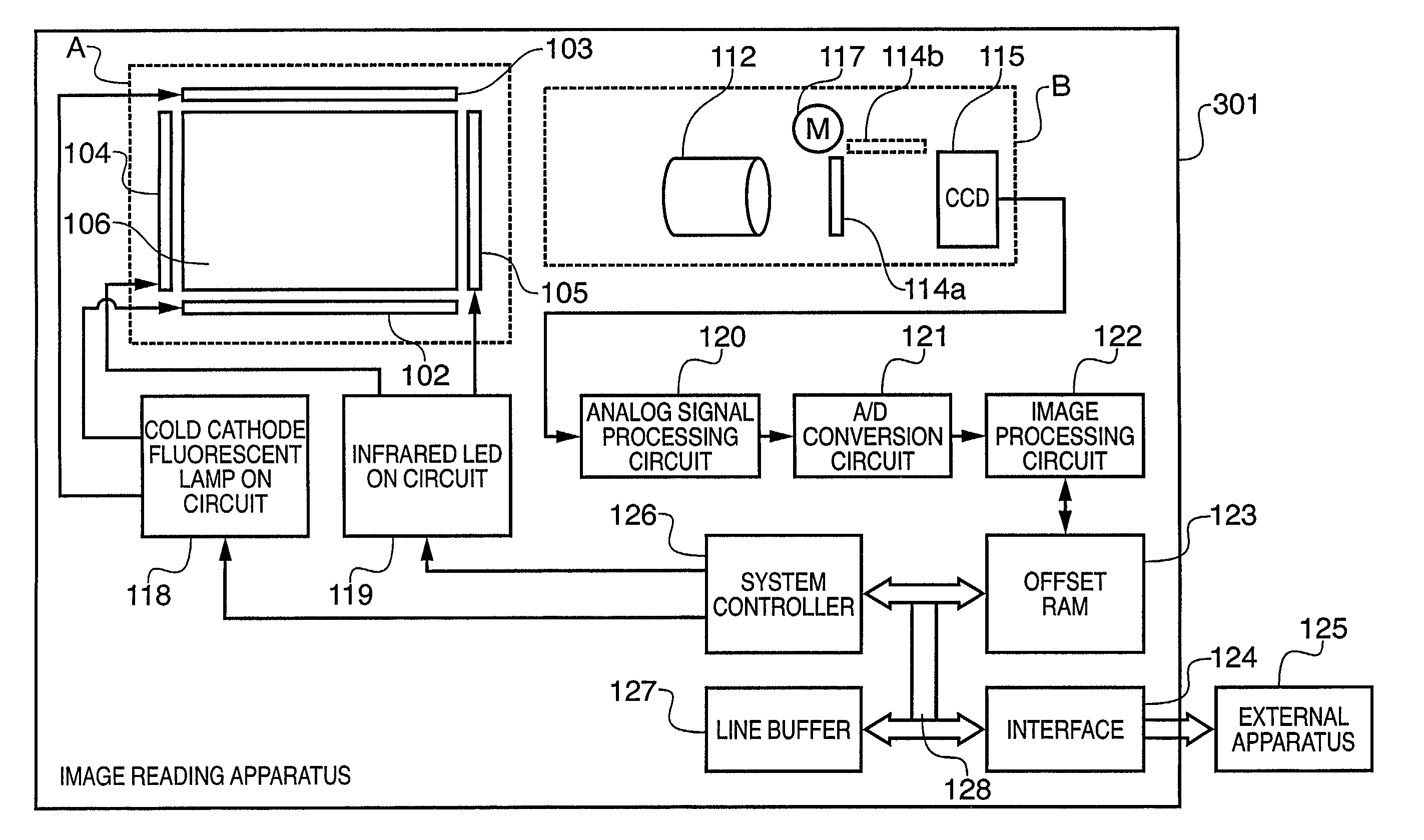
[0081]FIG. 3 is a block diagram showing the functional arrangement of a dust / scratch reducer 303 for performing dust / scratch reduction for an image signal output from the image reading apparatus 301 of the first embodiment in the personal computer 125. The dust / scratch reducer 303 in FIG. 3 may be incorporated in the image reading apparatus 301.

[0082]In FIG. 3, reference numeral 321 denotes an interface (I / F) for inputting image data obtained by reading a document by the image reading apparatus 301; 322, a visible light image memory for storing a visible light image obtained by reading a document by using the cold cathode fluorescent lamps 102 and 103; 323, an infrared image memory for storing an infrared image obtained by reading a document by using the infrared LED arrays 104 and 105; 325, a dust / scratch detection unit; 326, a dust / scratch reduction unit; 331, a magnification correction unit; 332, a positional shift correction unit; and 333, a reflection correction unit.

[0083]An o...

second embodiment

[0103]Transparent document reading operation including dust / scratch reduction in the second embodiment will be explained in detail with reference to the flow chart of FIG. 7.

[0104]In step S201, the reflecting document illumination lamp 145 and infrared lamp 151 in FIG. 26 are turned off, and the transparent document illumination lamp 144 is turned on. An illumination light beam from the transparent document illumination lamp 144 is uniformly diffused by a diffusion plate 143. The diffused light beam passes through a transparent document 142. The transmitted light beam is reflected by a mirror 147 and inverted-V mirrors 148, passes through an imaging lens 149, and is projected onto a CCD 150. The image projected onto the CCD 150 is converted into an electrical signal, which is temporarily stored in the image memory 22 via the I / F 21 in FIG. 6. If the transparent document is a negative film, a reversal process is performed to obtain a positive image (to be referred to as a “normal ima...

third embodiment

[0130]The third embodiment will be described with reference to FIGS. 13A to 13E, 14, and 15A to 15D. FIG. 13A shows a state in which dust 502 is on a film 501. FIG. 13B shows the gray level when the portion of FIG. 13A is read at a designated resolution by turning on a transparent document illumination lamp 144 shown in FIG. 26. Dust does not transmit any light, so the gray level distribution has a concave-up shape. FIG. 13C shows the gray level when the portion of FIG. 13A is read by turning on an infrared lamp 151 shown in FIG. 26, and particularly when this portion is read at a resolution much lower than a designated resolution. In this case, the portion of FIG. 13A is read at a very low resolution, and the gray level changes gradually. A gray level L2 having a difference by a value (or value set by a histogram and gray level analysis) set in advance as a predetermined level ΔL12 from a gray level L1 free from the dust / scratch influence in the infrared image view of FIG. 13C is s...


PUM

PropertyMeasurementUnit
peak wavelengthaaaaaaaaaa
infrared wavelengthaaaaaaaaaa

Abstract

An image reading apparatus having a visible light source for emitting visible light, an invisible light source for emitting invisible light, an imaging optical system for irradiating a document by these light sources to form optical images of the document, and a CCD for photoelectrically converting the optical images of the document turns on the visible light source to acquire a visible light image signal by the CCD. Then, the apparatus turns on the invisible light source to acquire an invisible light image signal by the CCD. After the invisible light image signal is acquired, the apparatus turns off the invisible light source, and turns on the visible light source regardless of whether to read the document.

Description

FIELD OF THE INVENTION[0001]The present invention relates to an image processing method, image processing apparatus, and image reading apparatus and, more particularly, to an image processing method, image processing apparatus, and image reading apparatus for correcting any defects of a read transparent document due to dust, scratches, and the like.BACKGROUND OF THE INVENTION[0002]FIG. 25 shows a schematic arrangement in a conventional transparent document image reading apparatus. Referring to FIG. 25, a transparent document 142 such as a positive film, negative film, or the like placed on a platen glass 141 is illuminated with light emitted by a transparent document illumination lamp 144 via a diffusion plate 143 set above the document, and light transmitted through the transparent document 142 is guided to a CCD 150 via a mirror 147, inverted-V mirrors 148, and imaging lens 149. The light is converted by the CCD 150 on which a large number of solid-state image sensing elements lin...

Claims


Application Information

Patent Timeline
Patent Type & Authority Patents(United States)
IPC IPC(8): G06K9/40G01N21/86H04N1/393H04N1/40H04N1/48
CPCH04N1/40056H04N1/486H04N1/4097H04N23/811
Inventor TAKAYAMA, TSUTOMUHANABUSA, MITSUGUKASHIWAZAKI, ATSUKOKINUMURA, KENGO
Owner CANON KK
Why Eureka
Try Eureka