Flexible high-temperature ultrabarrier

a high-temperature ultrabarrier and flexible technology, applied in the direction of instruments, final product manufacturing, sustainable manufacturing/processing, etc., can solve the problems of metals typically lacking transparency, glass lacking flexibility, and organic light emitting devices (oleds) suffering reduced output or premature failur

Inactive Publication Date: 2006-03-28
3M INNOVATIVE PROPERTIES CO
View PDF43 Cites 484 Cited by
  • Summary
  • Abstract
  • Description
  • Claims
  • Application Information

AI Technical Summary

Problems solved by technology

Organic light emitting devices (OLEDs) can suffer reduced output or premature failure when exposed to water vapor or oxygen.
Metals and glasses have been used to encapsulate and prolong the life of OLED devices, but metals typically lack transparency and glass lacks flexibility.
A flexible polymeric barrier film that exhibited low permeability to water vapor and oxygen would be especially useful, but despite intense industrial effort only limited success has been attained thus far.

Method used


Image

  • Flexible high-temperature ultrabarrier
  • Flexible high-temperature ultrabarrier
  • Flexible high-temperature ultrabarrier

Examples


example 1

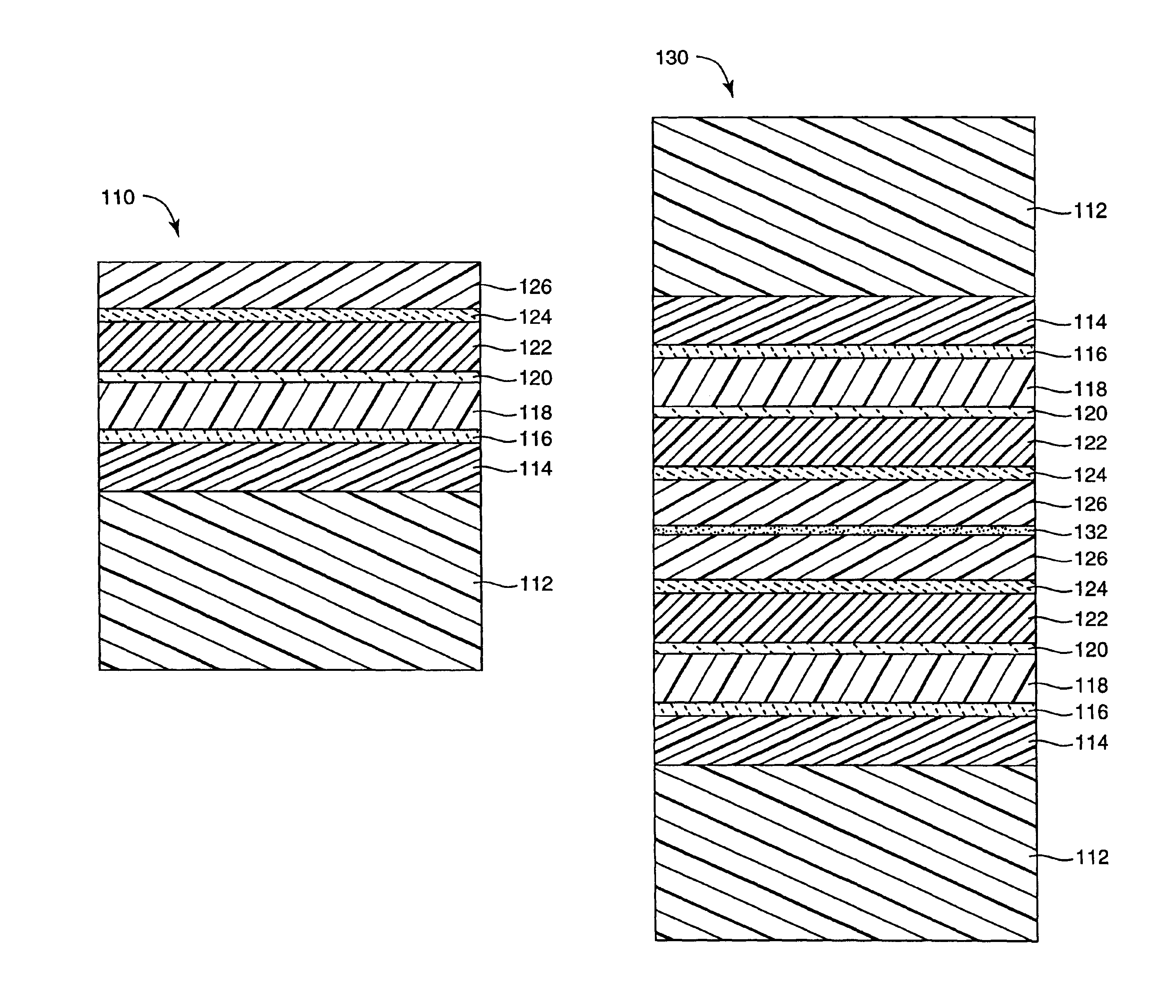
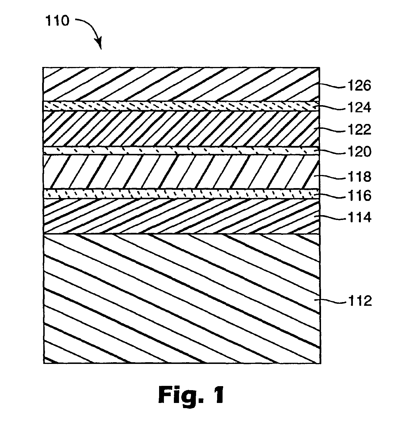
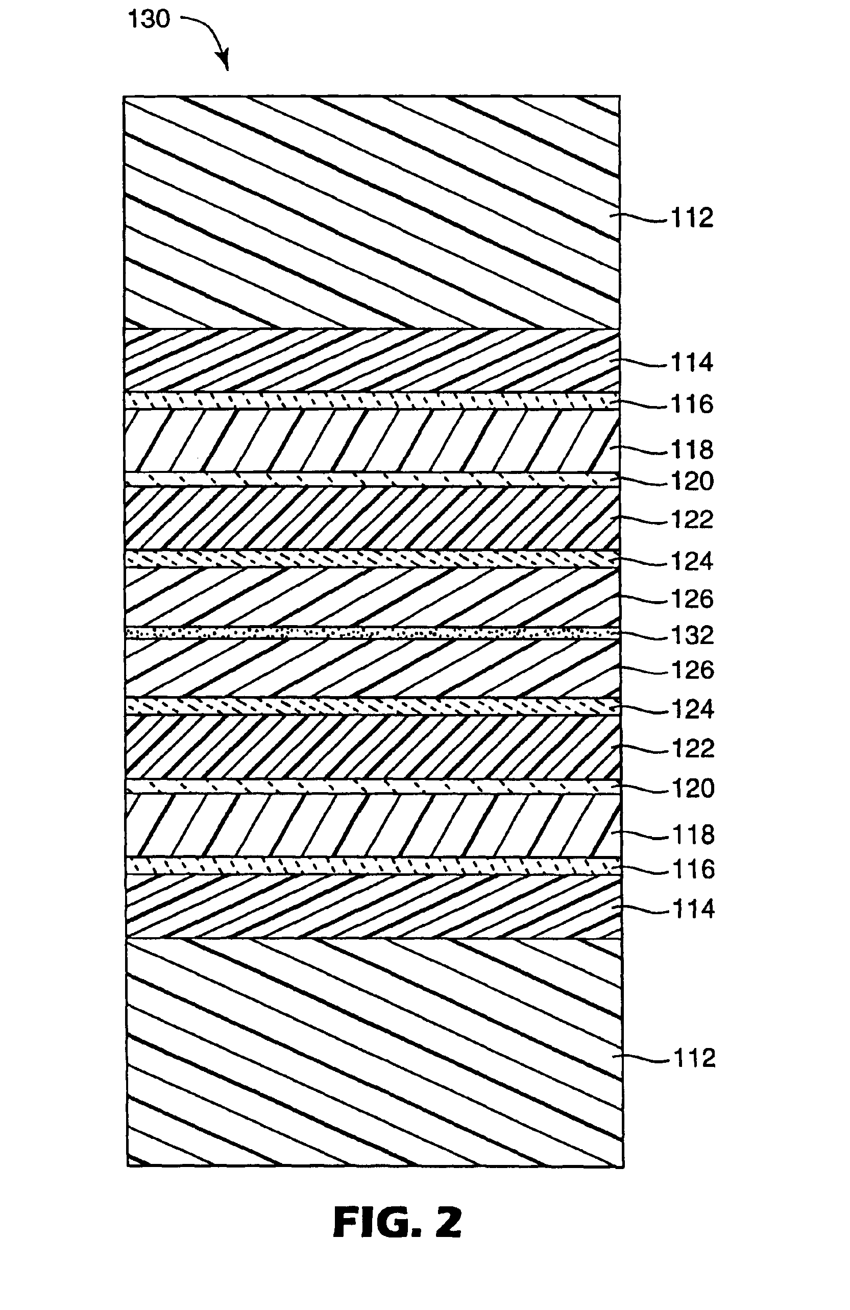
[0043]A polyethylene naphthalate (“PEN”) support film was covered with a stack of acrylate and indium tin oxide (“ITO”) layers arranged in a seven layer alternating acrylate / ITO / acrylate / ITO / acrylate / ITO / acrylate configuration. The individual layers were formed as follows:

[0044](Layer 1) A 91 meter long roll of 0.127 mm thick×508 mm wide KALADEX™ 1020 PEN film (commercially available from Dupont-Teijin Films, Tg=120° C.) was loaded into a roll-to-roll vacuum processing chamber. The chamber was pumped down to a pressure of 8×10⁻⁶ torr. The film was treated with a nitrogen plasma operating at 600 W using a titanium cathode, using a web speed of 9.1 meters / min and maintaining the backside of the film in contact with a coating drum chilled to 0° C. Immediately after the plasma treatment and while the film was still in contact with the drum, the plasma-treated film surface was coated with an acrylate mixture prepared by combining 97% IRR-214 cyclic diacrylate (commercially available from...

example 2

[0053]A seven layer stack was prepared in the same manner as Example 1, but using SR-368D mixed acrylate mixture (commercially available from Sartomer Co. as a 50:50 mixture of SR-351 trimethylolpropane triacrylate and SR-368 tris (2-hydroxyethyl) isocyanurate triacrylate) and using no plasma treatment in the formation of Layers 3, 5, and 7. The estimated Tg of SR-368D is 167° C., based on an arithmetic average of the 62° C. Tg of SR-351 and the 272° C. Tg of SR-368.

[0054]The resulting seven layer stack exhibited an average spectral transmission Tvis=68% measured at a 30° angle of incidence, and a WVTR (determined at 50° C. and 100% RH) that was below the 0.005 g / m2 / day lower detection limit rate of the WVTR testing system.

example 3

[0055]A seven layer stack was prepared in the same manner as Example 1, but using MELINEX™ 617 polyethylene terephthalate (“PET”) film substrate (commercially available from DuPont-Teijin Films, Tg=70° C.) and different acrylates. Tripropylene glycol diacrylate (“TRPGDA”, commercially available from UCB Chemicals, Tg=62° C.) was used as the Layer 1 acrylate. A mixture containing 97% TRPGDA and 3% EBECRYL 170 acrylated acidic adhesion promoter and having an estimated Tg=62° C., was used to form Layers 3, 5 and 7.

[0056]The resulting seven layer stack exhibited an average spectral transmission Tvis=71% measured at a 30° angle of incidence, and a WVTR (determined at 50° C. and 100% RH) of 0.036 g / m2 / day.


PUM

PropertyMeasurementUnit
RHaaaaaaaaaa
Tgaaaaaaaaaa
Tgaaaaaaaaaa

Abstract

A flexible barrier assembly having a flexible visible light-transmissive substrate having a Tg greater than or equal to that of heat-stabilized polyethylene terephthalate (“HSPET”) overcoated with a first polymer layer having a Tg greater than or equal to that of HSPET and further overcoated with at least two visible light-transmissive inorganic barrier layers separated by at least one second polymer layer having a Tg greater than or equal to that of HSPET can be used to mount, cover, encapsulate or form moisture- and oxygen-sensitive articles such as organic light emitting devices and light valves.

Description

[0001]This invention relates to barrier films and electronic devices.BACKGROUND[0002]Organic light emitting devices (OLEDs) can suffer reduced output or premature failure when exposed to water vapor or oxygen. Metals and glasses have been used to encapsulate and prolong the life of OLED devices, but metals typically lack transparency and glass lacks flexibility. Intensive efforts are underway to find alternative encapsulation materials for OLEDs and other electronic devices. A flexible polymeric barrier film that exhibited low permeability to water vapor and oxygen would be especially useful, but despite intense industrial effort only limited success has been attained thus far. References relating to flexible barrier films include U.S. Pat. No. 5,440,446 (Shaw et. al.), U.S. Pat. No. 5,530,581 (Cogan), U.S. Pat. No. 5,681,666 (Treger et al.), U.S. Pat. No. 5,686,360 (Harvey, III et al.), U.S. Pat. No. 5,736,207 (Walther et al.), U.S. Pat. No. 6,004,600 (Topolski et al.), U.S. Pat. N...

Claims


Application Information

Patent Timeline
Patent Type & Authority Patents(United States)
IPC IPC(8): B32B9/04B32B27/08B32B27/36G02F1/1333H01L51/00H01L51/52
CPCB32B27/08B32B27/36H01L51/0097H01L51/5256G02F1/1333H01L51/52Y10T428/264Y02E10/549Y10T428/10Y10T428/1036Y10T428/105H01L2251/5338Y10T428/31504Y10T428/31786Y10T428/31928Y10T428/3154Y10T428/31544C09K2323/035C09K2323/03C09K2323/00Y02P70/50H10K77/111H10K50/80H10K50/8445H10K2102/311B32B27/28
Inventor PADIYATH, RAGHUNATHROEHRIG, MARK A.
Owner 3M INNOVATIVE PROPERTIES CO
Why Eureka
Try Eureka