Apparatus and method for trellis encoding data for transmission in digital data transmission systems

a technology of digital data transmission system and trellis, which is applied in the field of bidirectional passband digital communication system, can solve the problems of degrading system performance and throughput, affecting the performance of the system, and affecting the spectral efficiency of the system, so as to achieve the effect of reducing the number of errors

Inactive Publication Date: 2006-03-28
GOOGLE TECH HLDG LLC
View PDF110 Cites 60 Cited by
  • Summary
  • Abstract
  • Description
  • Claims
  • Application Information

AI Technical Summary

Benefits of technology

[0018]In the preferred embodiment, the master carrier and master clock are recovered in the RUs and used to transmit data upstream along with preamble data preceding payload data. The preamble data from each RU is used by the central unit transceiver to generate an amplitude and phase correction factor for that RU. The signals from that RU are then demodulated using the CU master carrier and demultiplexed and detected using the CU master clock. Phase and amplitude errors in the detection process caused by latency and channel impairments are eliminated or reduced by using the phase and amplitude correction factors developed for this RU from its preamble data. Thus, there is no need for continuous tracking loops in the CU receiver to recover the clock and carrier used by each RU to transmit its data. This single master carrier and master clock concept and the frame synchronization provided by ranging, and the improved throughput and lower error rates provided by the equalization and power alignment processes taught herein are useful in any form of bidirectional digital data distributed communication system regardless of the form of encoding, multiplexing or modulation used. Examples of the types of multiplexing that can be used in such systems are CDMA, TDMA, inverse Fourier, DMT or any other system where orthogonal signals are used to encode each separate channel of data from a source such as sine and cosine signals etc.
[0035]The advantages over TDMA systems include less need for fast acquisition and correspondingly lower sensitivity to narrowband interference. Further, below a certain SNR, TDMA systems may fail altogether. Contention for certain channels and contention affecting adjacent can cause amplifier overload in TDMA systems and can cause severe throughput and performance problems. FDMA systems where each user gets a narrow upstream frequency slice is very susceptible to narrowband noise which can wipe out an entire channel. FDMA systems often try to avoid this problem with frequency reallocation. This complicates and raises the cost of the system by requiring more intelligence. Throughput is also adversely affected as nothing is sent while frequencies are reallocated. Guardbands between channels waste bandwidth, and frequency misalignment degrades FDMA systems.

Problems solved by technology

In these systems, the designers have chosen to ignore the phase of the received signal at the expense of some degradation of the system performance and throughput.
However, coherent systems are more complex since they require additional tracking loop circuitry at the receiver to recover the transmitted carrier and use the information so derived to steer the local oscillator so as to maintain its phase and frequency locked to the phase and frequency of the carrier.
The problem is that PLLs and negative feedback voltage controlled oscillators in tracking loops can and often do lose lock especially where there is rapid change in phase or frequency caused by conditions in the transmission media.
When a PLL or other tracking loop loses lock, the system goes out of synchronization and fails to communicate data—its sole purpose in life.
The problem with asynchronous transmission is the high overhead.
The overhead of 2–3 bits per character of 5–8 bits makes asynchronous transmission inefficient to transmit large volumes of data.
For example, a separate clock line can connect the transmitter and receiver, but this is impractical in many situations.
Again, complicated circuitry centered around a voltage controlled oscillator is needed to recover the clock.
Since PLLs and tracking loops are not always reliable, and add complication and expense to receivers, it is desirable to be able to get rid of them wherever possible.

Method used


Image

  • Apparatus and method for trellis encoding data for transmission in digital data transmission systems
  • Apparatus and method for trellis encoding data for transmission in digital data transmission systems
  • Apparatus and method for trellis encoding data for transmission in digital data transmission systems

Examples


specific examples

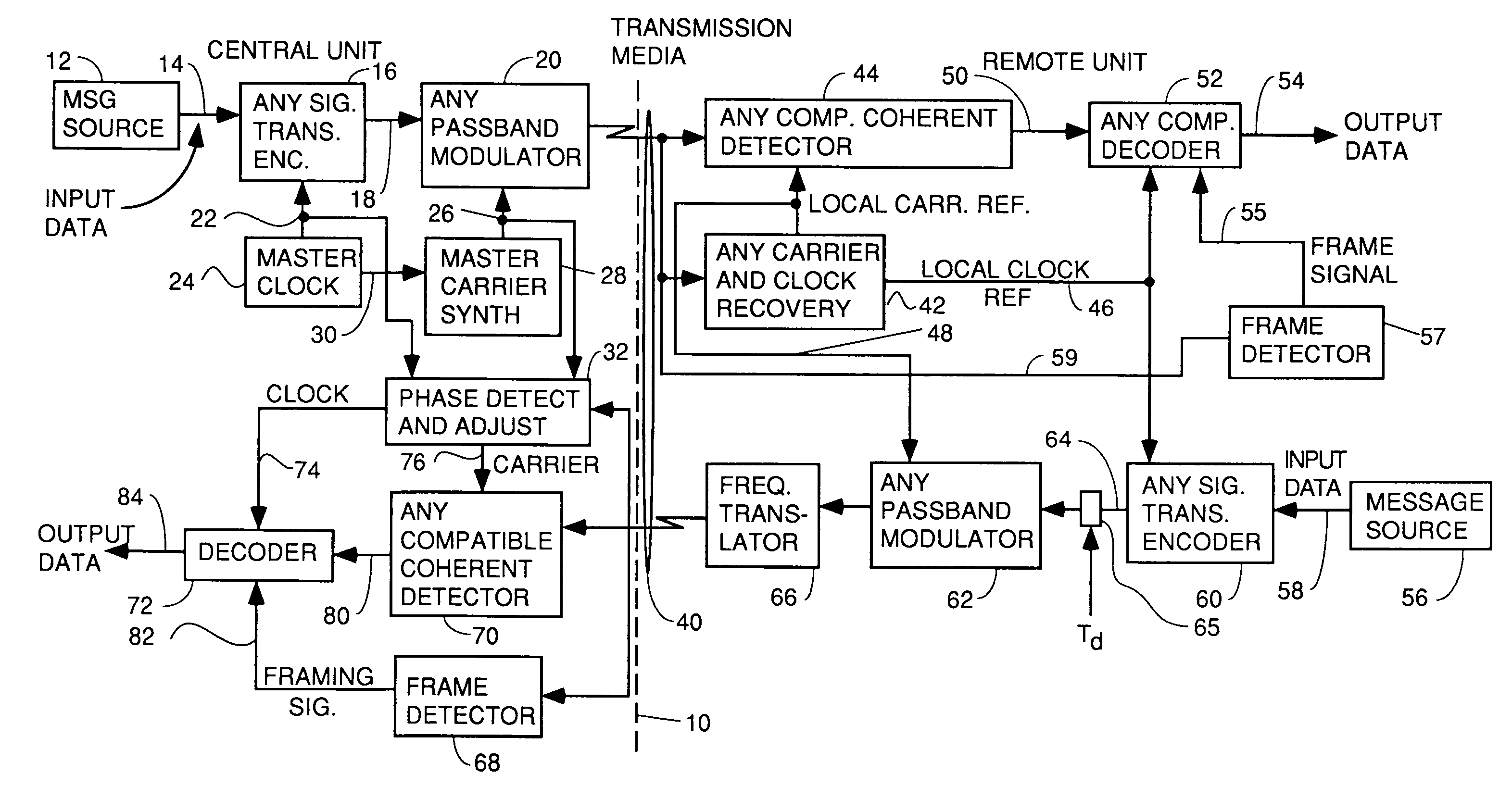
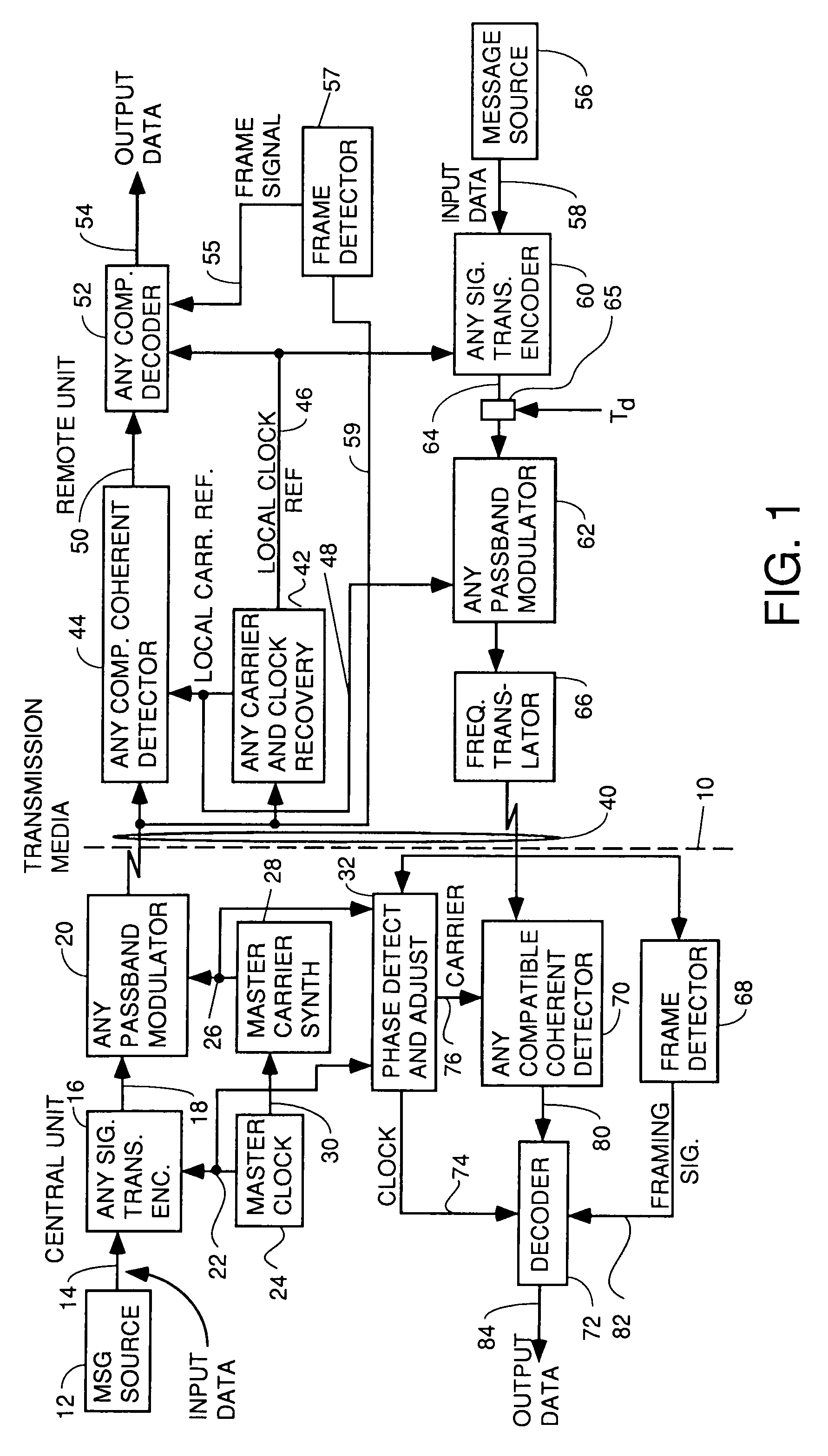
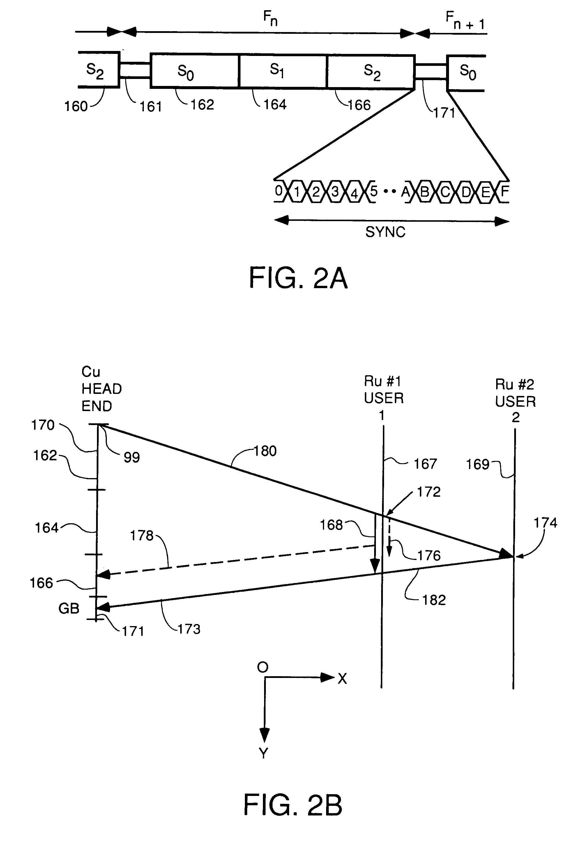
[0135]There follows some examples of specific systems that utilize the teachings of the invention. First an embodiment that uses synchronous code division multiple access is discussed. Synchronous code division multiple access in a distributed system requires that all frames from the remote units at different distributed locations arrive at the central unit receiver with their frame boundaries aligned in time. Accordingly, we start with a discussion of the ranging process which is carried out between each remote unit (hereafter RU) and the central unit (hereafter CU) so as to set a transmit frame timing delay for the remote unit which will result in proper frame alignment of that remote unit's frames.

[0136]Those skilled in the art will appreciate that the ranging processes described herein has applicability to any distributed data communication system which transmits data in frames regardless of the form of multiplexing or the form of modulation used. Likewise, the equalization proc...


PUM


Abstract

A system for bidirectional communication of digital data between a central unit and a remote unit wherein the need for tracking loops in the central unit has been eliminated. The central unit transmitter generates a master carrier and a master clock signal which are used to transmit downstream data to the remote units. The remote units recover the master carrier and master clock and synchronize local oscillators in each remote unit to these master carrier and master clock signals to generate reference carrier and clock signals for use by the remote unit receiver. These reference carrier and clock signals are also used by the remote unit transmitters to transmit upstream data to the central unit. The central unit receiver detects the phase difference between the reference carrier and clock signals from the remote units periodically and adjusts the phase of the master carrier and master clock signals for use by the central unit receiver to receive the upstream data.

Description

[0001]Divisional of prior application Ser. No. 08 / 895,612 filed Jul. 16, 1997 now U.S. Pat. No. 6,307,868.[0002]This application is a continuation-in-part application of U.S. patent application Ser. No. 08 / 684,243, filed Jul. 19, 1996, now U.S. Pat. No. 6,356,555, issued Mar. 12, 2002, invented by Shlomo Rakib and Yehuda Azenkot which was a continuation-in-part application of U.S. patent application Ser. No. 08 / 588,650, filed Jan. 19, 1996, now U.S. Pat. No. 5,793,759, issued Aug. 11, 1998, invented by Shlomo Rakib and Yehuda Azenkot, which was a continuation-in-part application of U.S. patent application Ser. No. 08 / 519,630, filed Aug. 25, 1995, invented by Shiomo Rakib and Yehuda Azenkot, now U.S. Pat. No. 5,768,269, issued Jun. 16, 1998, the contents of all of which are hereby incorporated by reference. This application is also a continuation-in-part application of a U.S. patent application entitled LOWER OVERHEAD METHOD FOR DATATRANSMISSION USING ATM AND SCDMA OVER HYBRID FIBER ...

Claims


Application Information

Patent Timeline
Patent Type & Authority Patents(United States)
IPC IPC(8): H04J1/00H03M13/25H03M13/41H04B1/707H04B1/7087H04B7/26H04H20/77H04H20/78H04J3/06H04J11/00H04J13/00H04J14/00H04L1/00H04L1/16H04L5/02H04L5/06H04L7/04H04L12/28H04L12/56H04L25/03H04L25/49H04L27/00H04L27/26H04L27/36H04N7/173H04N21/222H04N21/24H04N21/43H04N21/438
CPCH03M13/256H03M13/41H04B1/1027H04B1/707H04B1/7087H04B7/2668H04H20/78H04J3/0682H04J13/00H04J13/004H04L1/006H04L5/023H04L5/026H04L5/06H04L12/2801H04L25/03343H04L25/4921H04L27/0014H04L27/362H04N7/10H04N7/17309H04N7/54H04N21/2221H04N21/2408H04N21/4305H04N21/4383H04W48/16H03M13/39H04W74/0866H04B2201/709709H04H20/77H04J3/0602H04J3/0608H04J3/0638H04J14/007H04L1/16H04L7/041H04L25/03057H04L27/2656H04L27/2657H04L27/2662H04L2025/03414H04L2027/0083H04L2027/0087H04W24/00H04W56/00
Inventor RAKIB, SELIM SHLOMOAZENKOT, YEHUDA
Owner GOOGLE TECH HLDG LLC
Why Eureka
Try Eureka