Fiber laser

a fiber laser and laser technology, applied in the field of fiber lasers, can solve the problems of large amplification cross-section, longer excited state duration, small non-radiative decay rate, etc., and achieve the effect of high reflectivity

Inactive Publication Date: 2006-04-11
EVOTEC TECH GMBH
View PDF48 Cites 124 Cited by
  • Summary
  • Abstract
  • Description
  • Claims
  • Application Information

AI Technical Summary

Benefits of technology

[0014]Preferably, the resonator unit comprises a collimating lens for setting the wavelength range fed back into the fiber, said collimating lens being longitudinally shiftable relative to the exit end of the fiber. Shifting of the collimating lens allows individual wavelength ranges reflected by the resonator mirror or the resonator mirrors to be coupled into the fiber. The collimating lens can preferably be used in such a way that it serves for controlling the emission in the corresponding wavelength ranges.
[0015]Preferably, a coupling-in mirror transparent to the wavelength range of the pump light is provided at the entrance end of the fiber. To allow setting of the efficiency of the radiation amplification in the range of the desired emission wavelength of the fiber, the coupling-in mirror offers, on the side facing the entrance end of the fiber, an adequately high reflectivity to the emission wavelength range of the fiber laser.

Problems solved by technology

In contrast to silicate glasses fluorite glasses have smaller effective photon energies, which results in smaller rates of non-radiative decay, longer durations of excited states and larger amplification cross-sections.

Method used


Image

  • Fiber laser
  • Fiber laser
  • Fiber laser

Examples


Embodiment Construction

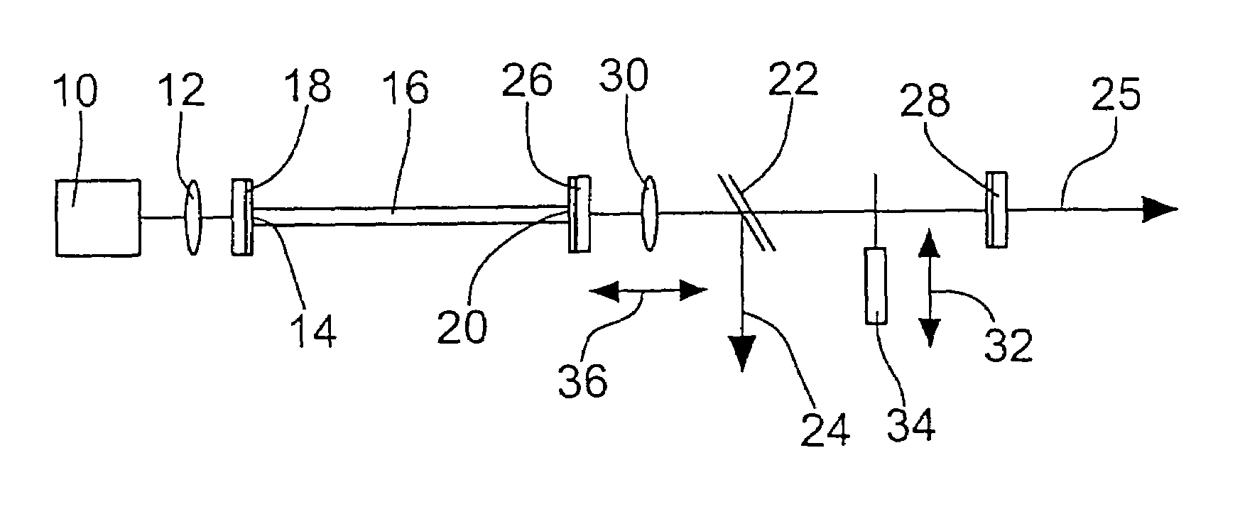
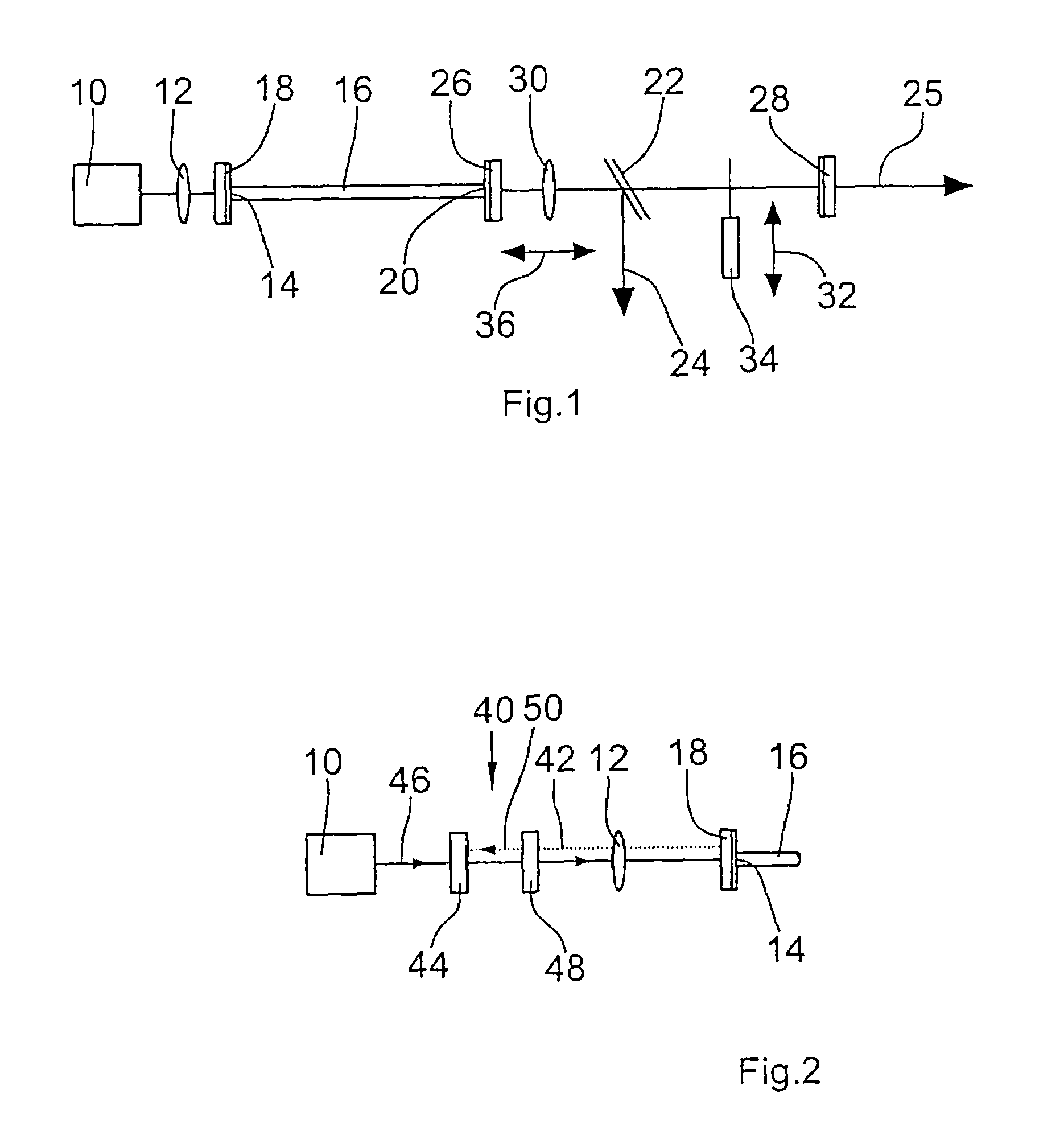
[0042]The fiber laser according to the invention comprises a pump light source 10 which is preferably a laser diode. The light emitted by the pump light source 10 is coupled by a lens 12 into an entrance end 14 of a fiber 16. For this purpose, a coupling-in mirror 18 is provided at the entrance end 14, said mirror preferably being glued to the fiber end.

[0043]The laser light coupled into the fiber 16 excites the ions contained in the fiber 16 such that said ions emit laser light with the desired wavelength. The laser light emerges from the fiber at an exit end 20 of the fiber 16 and can be coupled out by a semi-transmitting mirror 22 in the direction indicated by arrow 24 or by a mirror 28 in the direction indicated by arrow 25.

[0044]According to the invention, a resonator unit is provided via which a portion of the light emerging from the exit end 20 of the fiber 16 is fed back into the fiber 16. For this purpose, the resonator unit comprises a first resonator mirror 26 which is pr...


PUM


Abstract

A fiber laser with a fiber for laser light generation having an entrance end and an exit end comprises a pump light source for generating pump light to be coupled via the entrance side into the fiber. At the exit end of the fiber a first resonator mirror is provided which is highly reflecting for the laser light to be generated in the wavelength range with the smallest light amplification and to the light of the pump light source. Spaced from the first resonator mirror a second resonator mirror is provided via which light of further wavelength ranges can be fed back into the fiber with the aid of a collimating lens.

Description

FIELD OF THE INVENTION[0001]The invention relates to a fiber laser having a doped optical fiber for laser light generation.DISCUSSION OF THE BACKGROUND ART[0002]In a fiber laser the laser-active medium is incorporated in a light waveguide. Laser activity of the fiber is attained in particular by doping the fiber core with ions of rare earths. In numerous laser transitions of rare earth ions it was possible for the first time to observe laser emission in fiber lasers, in particular since it has been possible to use, besides silicate glasses, fluorite glasses, above all fluor zirconate glass ZBLAN, as a host material. In contrast to silicate glasses fluorite glasses have smaller effective photon energies, which results in smaller rates of non-radiative decay, longer durations of excited states and larger amplification cross-sections. Fluorite glasses allow high quantum efficiencies and an efficient excitation into elevated energy levels to be attained by absorption out of excited stat...

Claims


Application Information

Patent Timeline
Patent Type & Authority Patents(United States)
IPC IPC(8): H01S3/30H01S3/082H01S3/067H01S3/08H01S3/081H01S3/094H01S3/105
CPCH01S3/067H01S3/06704H01S3/08H01S3/1062H01S3/094003H01S3/105H01S3/081
Inventor BAEV, VALERISTARK, ARNOLDSALEWSKI, STEFANTHURAU, WOLFGANGTOSCHEK, PETER
Owner EVOTEC TECH GMBH
Why Eureka
Try Eureka