Some of the limitations are imposed by the transmission or storage medium or other technological deficiencies; other limitations are the result of environmental issues.
For example, the amplification necessary to hear the quietest portions of an
audio signal may result in maximum amplitudes that are undesirably loud.
Conversely, amplitudes allowing loud portions of an audio signal to be heard at a comfortable level, may result in not being able to hear quiet portions of the signal.
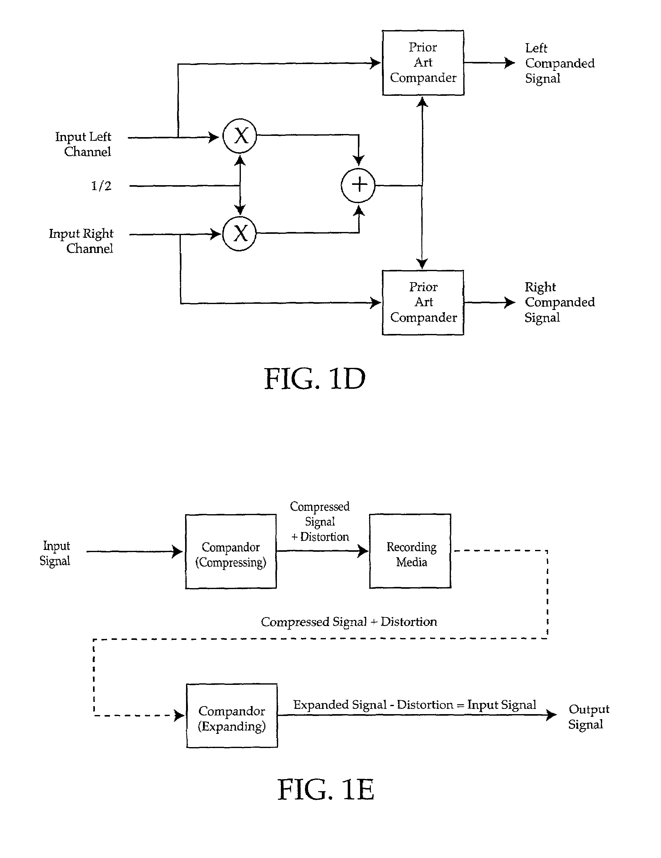
The input signal mixing typically results in additional distortion since the
adjacent channel signal is partly controlling the compander gain.
It also typically results in one channel being under-amplified and the other channel being over-amplified which can result in clipping distortion.
Broadcast or recording restrictions or other technological limitations often mandate that the
maximum amplitude range of a signal be restricted, and as a result signals are compressed to remain within those restrictions and limitations.
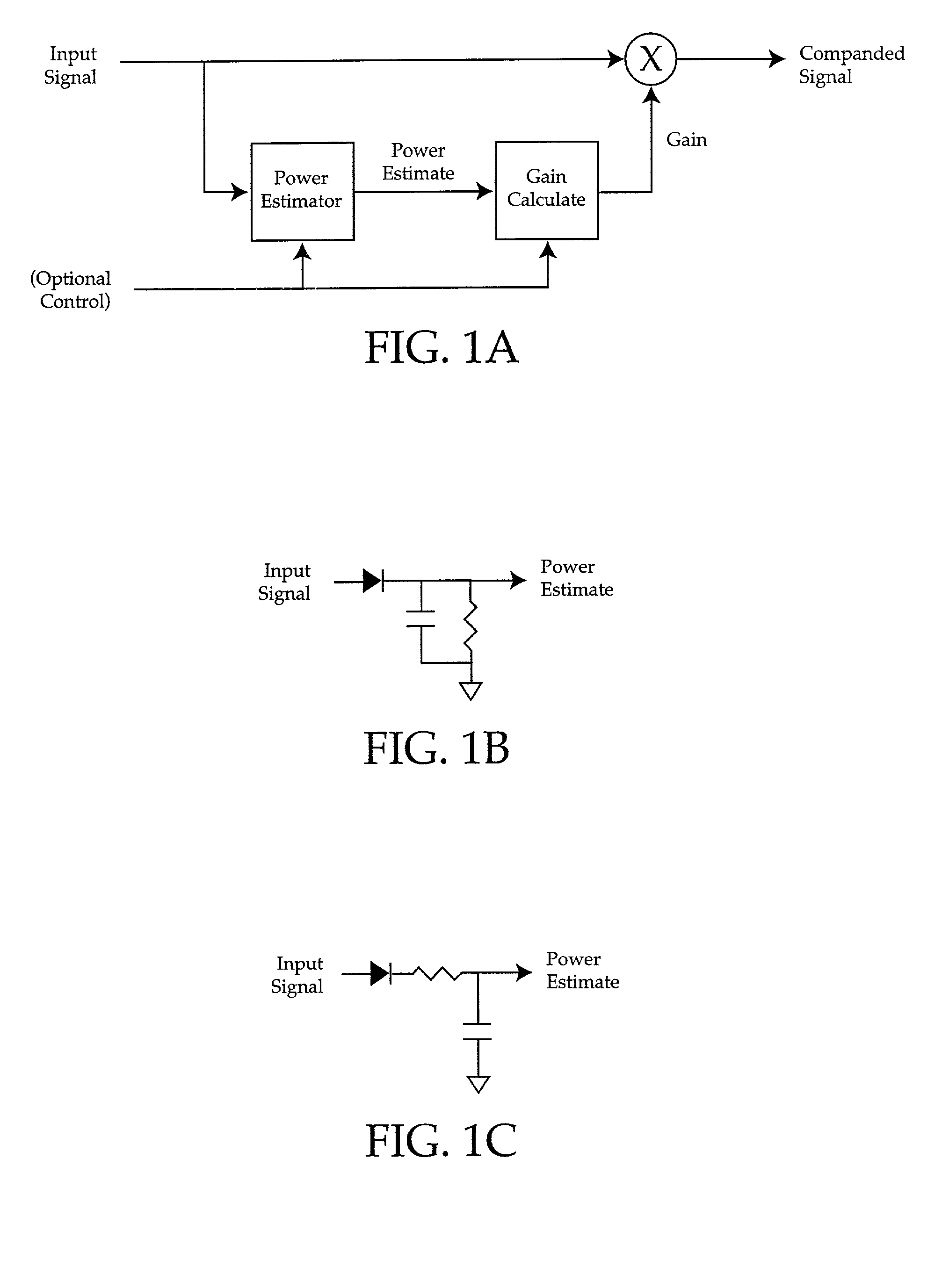
Thus a compressor and expander pair can be used to cancel out
low frequency distortion, but do not and cannot function as a standalone compressor or expander.
One common limitation of prior art audio
signal processing systems is that it is often difficult for a listener to comfortably hear all portions of an audio signal due to environmental audio
noise.
Environmental noise is transient and often unpredictable in nature, which makes manual adjustment to compensate for it particularly difficult.
If the user manually increases the volume for times when the signal cannot be heard due to loud
transient noise, the volume will be too loud once when the noise has subsided or the audio signal becomes greater in amplitude.
This problem occurs in many situations, usually (though not always) involving outdoors or mobile environments such as a car stereo, a
cellular telephone used in public places, a portable radio used during a public sporting event, or home theater systems.
This type of prior art solutions provides no means of calibration of the circuitry to the acoustic environment making their proper operation unpredictable.
They also do not satisfactorily address problems with variations in the audio source such as long silent pauses in the audio signal, uncontrolled
positive feedback known as gain chase, room acoustic resonances that appear as false noise, or allow changing the minimum
signal to noise ratio of the
system.
Further, they have an inadequate response to noise in that some respond too quickly, reacting to phone ringers and short bursts of speech, while others have too long and inaccurate a response.
Prior art solutions also do not allow the user to select the signal or noise priority so that if the noise is speech, the
signal source will be reduced instead of increased.
The signal necessary to provide adequate sound in one location, often results in sounds that are either too loud or quiet in other areas.
Prior art solutions have no automatic adjustments and require manual adjustments with little or no explanation.
While this technique will work for any particular frequency, it is not able to maintain a 90-degree separation over all frequencies.Beard U.S. Pat. No. 4,169,219 (1979) teaches the use of an analog, low-pass-filter
delay-buffer in implementing a compressor-expansion pair, for recording a compressed signal that subsequently would be expanded upon being played.
It is unsuitable for standalone use due to significant distortion of low frequency signals.Bethards U.S. Pat. No. 4,216,427 (1980) instructs in the use of an adaptive audio compressor using analog techniques for restricting subsequent RF
signal modulation.
This technique provides unacceptable distortion of
wide band audio signals.Unagami et al.
Its use of a low-pass filter results in high distortion at low frequencies, and its overall design causes undesirable signal clipping.Rosback U.S. Pat. No. 4,641,361 (1987) instructs in the use of an analog, multi-
frequency band, automatic gain circuit that makes use of a peak clipper to reduce overall gain.
Gain is changed continuously, resulting in distortion at low frequencies.Bloy et al.
This technique undesirably amplifies the signal
noise floor.
Changes in gain are made continuously, resulting in inherent signal distortion.U.S. Pat. No. 4,322,579 to Kleis et al.
It has the
disadvantage that it always amplifies the signal, when compressing the signal would provide superior comfort to the user.
The difficulty with this patent is that it requires that the
microphone only detect noise, and thus places it in a vehicle engine compartment, when in fact,
wind noise is often the dominant source of
environmental noise, resulting in the circuit not solving the stated problem.U.S. Pat. No. 4,882,762 to Waldhaner (1989) teaches the use of a programmable multi-band
compression system for hearing aids.
It does not provide variable, automatic compensation of the signal in the presence of
environmental noise, since it has no way to detect or distinguish this noise.U.S. Pat. No. 4,891,837 to Walker et al.
The
disadvantage of this technique is that a
sample and hold circuit must be used to avoid a noise problem whenever the audio input signal goes silent.U.S. Pat. No. 5,107,539 to Kato et al.
This circuit has several disadvantages, long silent pauses in the audio signal will result in undesirably loud amplification, and it does no compression of the signal, resulting in situations where the audio signal becomes too loud.U.S. Pat. No. 5,172,358 to Kimura (1992) shows the usage of a
digital signal processor to boost low and high frequencies depending on the average amount of
sound pressure.
No means are provided to calibrate the actual
sound pressure with the levels inside the circuit.
Adaptive and least means square algorithms are computationally intensive and in certain situations can add undesirable amounts of distortion to a signal.
The main distinctive feature is the use of a
delay line that is ineffective due to room
reverberation and variations caused by changing
microphone position.
This method works for fixed delays, but does not function well in situations where there is considerable phase
delay, signal dispersion or echoes.
No signal companding is performed, resulting in circumstances where the output volume is unacceptably loud.
It does not address
normal mode resonances due to
room acoustics providing incorrect calibration.U.S. Pat. No. 4558460 to Tanaka, et al.
This will not work in a non-automotive setting since the
noise compensation is dependent on vehicle speed and not
environmental noise.As will be appreciated from the foregoing discussion, the prior art companders suffer from a number of disadvantages.
All produce high levels of signal distortion at low frequencies.
Using
multiple frequency band compander techniques to reduce distortion requires significant additional processing requirements.
Many rely upon a compressor and expander pair to cancel out low frequency distortion, and do not and cannot function as a standalone compressor or expander.
Many of the companders are implemented using analog designs that do not address considerations necessary for the use of
digital signal processors, or take
advantage of their capabilities.
Some use multiple channel compander designs with input signal mixing that result in inter-
channel modulation distortion and output clipping.
Most compander designs use fixed
attack and release times or use a plurality of fixed
attack and
release time-constant filters, that can result in additional signal distortion or limited operating range.
Further, prior art noise compensators suffer from gain chase problems, inadequate and inaccurate response to noise, a lack of signal or noise priority choice, and no means to vary the output
signal to noise ratio.
Prior art systems typically require redundant equipment and do not provide automatic adjustments.
In summary, existing inventions are ineffective due to inherent design limitations.

