Internal combustion engines for hybrid powertrain

a hybrid powertrain and internal combustion engine technology, applied in the direction of machines/engines, output power, electric devices, etc., can solve the problems of little effort applied to the development and integration of internal combustion engines to optimize, and achieve the effects of reducing exhaust emissions, reducing power output and fuel economy of engines, and reducing pumping work

Inactive Publication Date: 2006-04-18
GREEN VISION TECH
View PDF19 Cites 59 Cited by
  • Summary
  • Abstract
  • Description
  • Claims
  • Application Information

AI Technical Summary

Benefits of technology

[0011]This strategy requires a fuel-scheduling map for steady state and transient operations of the diesel engine, as well as the functional relationship maps between the diesel engine and the electric motor. The fuel injection system of the diesel engine has multiple injection event capability such as, for example, pilot injection, main injection, post injection, and rate shaping capabilities, (i.e., triangle, boot, square etc.). The fuel schedule map will specify the injection timing, rate shaping, injection pressure and quantity for best engine fuel economy, emission control, and drivability.
[0012]One aspect of the present invention is to power the engine accessories with the battery of the hybrid powertrain. The engine components of diesel engines are typically driven by the crankshaft of the engine, which reduces the power output and fuel economy of the engine. The present invention uses the battery power, which can be generated during the vehicle deceleration, to drive various engine components such as a cooling fan, a water pump, an alternator, an air compressor, a power steering pump and / or an air conditioning compressor.
[0013]Another aspect of the present invention is to apply the variable valve timing capability of the diesel engine to reduce the pumping work during the electric motor only mode, to perform cylinder cut-out, and to re-circulate EGR internally by delaying the exhaust valve closing and / or by early intake valve opening to reduce exhaust emissions (variable intake valve closing for increased compression ratio and / or Miller cycle operation).
[0014]A further aspect of the invention is to use the battery power to heat the catalytic converter to increase the catalyst efficiency. Efficiency of the after treatment device such as, for example, an NOx absorber and active lean NOx, are temperature dependent. The converter efficiency is decreased during partial load operation and at start up of the engine due to lower exhaust temperature. By externally heating the catalyst through a battery-powered heater, the catalyst maintains at its optimal conversion efficiency to reduce exhaust emissions.
[0015]The fourth aspect of the invention is to open the exhaust valve during the compression stroke to perform compression release braking in combination with the regenerative braking of the electric motor to control vehicle speed and to prevent overcharge of the battery.
[0016]The fifth aspect of this invention to use motor assisted turbocharger during acceleration to improve the turbo charger responsiveness. The motor is powered the battery of the hybrid powertrain.

Problems solved by technology

However, when the vehicle must be accelerated or decelerated at a rate that cannot be accomplished by the internal combustion engine alone, or if the drive efficiency of the engine would be degraded if only the internal combustion engine were used, the regenerative brake / motor, which is mechanically connected to the internal combustion engine, operates as an electric motor (on acceleration) or as a regenerative brake (on deceleration) to meet the required rate of acceleration or deceleration through the combined output of the internal combustion engine and the regenerative brake / motor.
Unfortunately, little efforts have been applied to the development and integration of the internal combustion engines to optimize the benefits of the hybrid powertrain for lower cost, better fuel economy and lower exhaust emissions, especially, for the heavy-duty diesel engines for the urban and on-highway truck and bus applications.

Method used


Image

  • Internal combustion engines for hybrid powertrain
  • Internal combustion engines for hybrid powertrain
  • Internal combustion engines for hybrid powertrain

Examples


Embodiment Construction

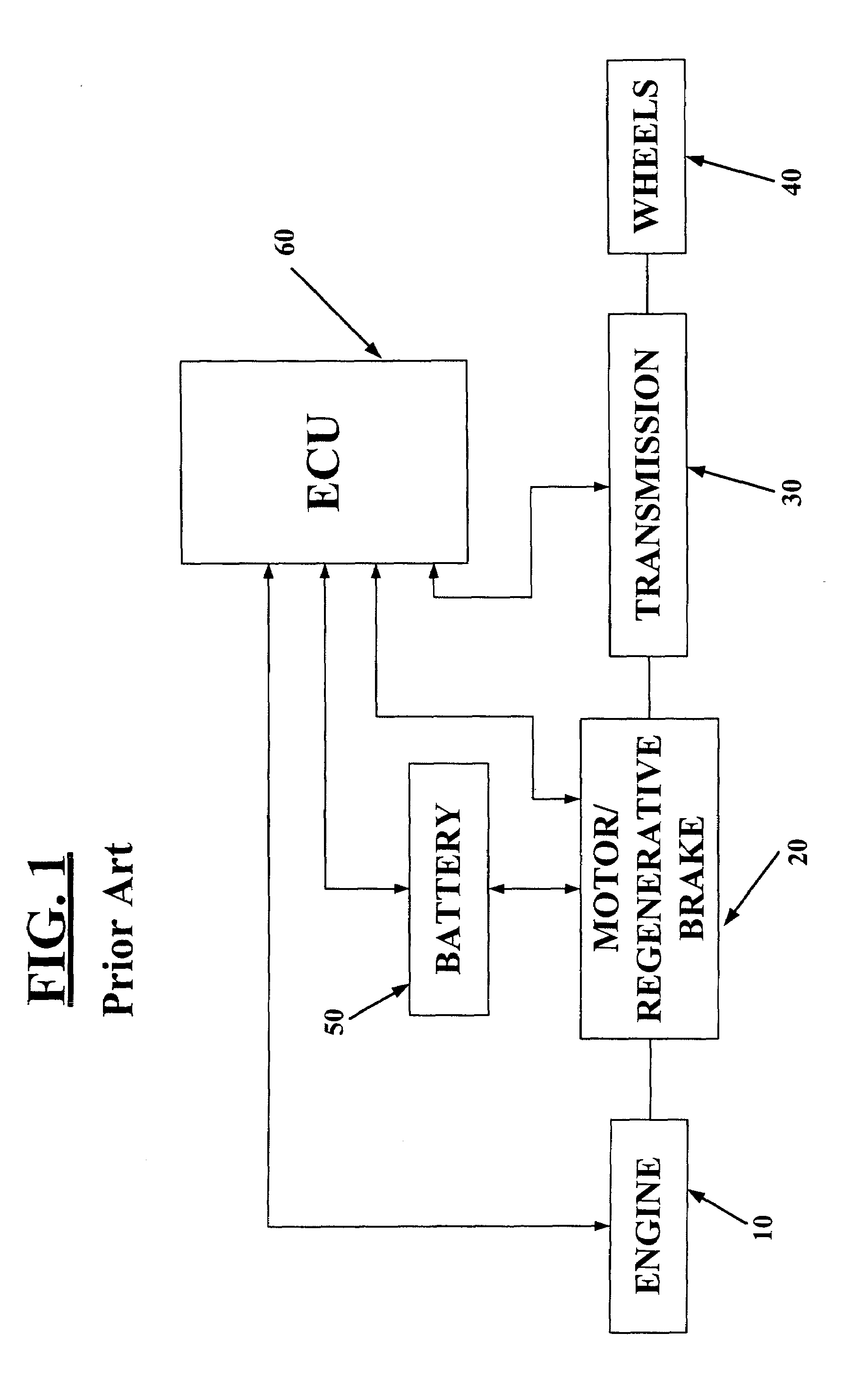
[0031]A schematic of a conventional serial hybrid powertrain is shown in FIG. 1. The numeral 10 designates a turbocharged diesel engine for use in a vehicle drivetrain. A motor / regenerative brake is shown at 20. Both diesel engine 10 and motor / regenerative brake 20 are connected to a multiple ratio transmission 30. Transmission 30 is mechanically connected to a pair of vehicle driving wheels 40. A battery 50 serves as an energy storage device which is electrically connected to motor / regenerative brake 20. An electronic controller unit 60 is coupled to the engine 10, the motor / regenerative brake 20, the transmission 30 and the battery 50 and controls the overall operation of the drivetrain.

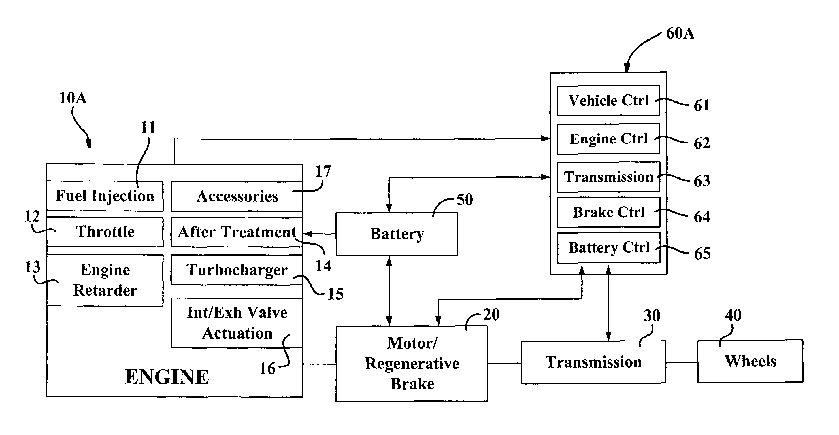
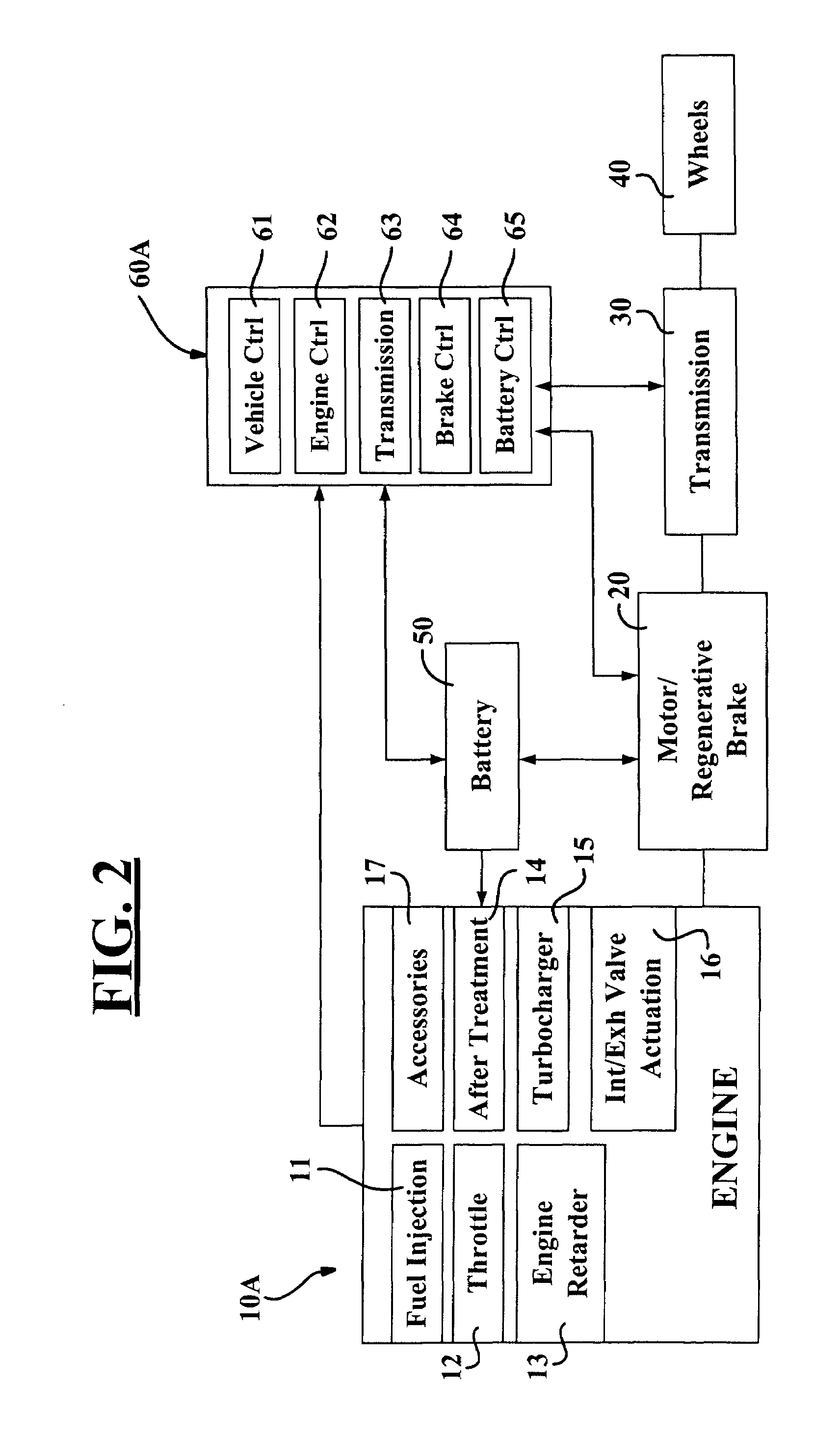
[0032]Referring to FIG. 2, a drivetrain constructed in accordance with the teachings of the present invention is illustrated to include an integrated internal combustion engine 10A. Engine 10A can include various controllable systems including a fuel injection system 11, a throttle system 12, an en...


PUM


Abstract

A hybrid powertrain and method for operating same in which the operation of the engine is modified to effect an improvement in the fuel economy and/or emissions performance of the hybrid powertrain. In one embodiment, the battery of the powertrain is employed to provide auxiliary heat to an engine aftertreatment system to thereby improve the effectiveness of the aftertreatment system. In another embodiment, various components of the engine, such as a water pump, are wholly or partly operated by electric motors that receive power from the battery of the powertrain. In another embodiment, engine braking can be employed in situations where regenerative braking does not provide sufficient braking torque. In a further embodiment, the engine valves may be selectively opened to reduce pumping losses associated with the back-driving of the engine.

Description

CROSS-REFERENCE TO RELATED APPLICATIONS[0001]This application claims the benefit of U.S. Provisional Application No. 60 / 355,546, filed on Feb. 8, 2002.FIELD OF THE INVENTION[0002]The invention relates to hybrid powertrains and more specifically to a method for improving fuel economy and / or reducing exhaust emissions in internal combustion engines for use in hybrid powertrains.BACKGROUND OF THE INVENTION[0003]The recent development of hybrid powertrains in the automotive industry has demonstrated encouraging results for reductions in fuel consumption and exhaust emissions. A vehicle with a hybrid powertrain usually includes an internal combustion engine, an electric generator, an electric motor, a battery and other equipment. In series hybrid vehicles, the generator is driven by the mechanical output of the internal combustion engine. The output of the generator is then combined with the output of the battery to drive the electric motor, such that the mechanical output of the motor d...

Claims


Application Information

Patent Timeline
Patent Type & Authority Patents(United States)
IPC IPC(8): B60K1/00B60K6/48B60K6/485B60L50/15B60W10/06B60W10/08B60W20/00F01N3/08F01N3/20F02B37/00F02B37/24F02D13/02F02D41/02F02D41/40F02M25/07
CPCB60K6/48B60W10/06B60W10/08B60W20/00F01N3/0842F01N3/0871F01N3/2013F02B37/24F02D13/0215F02D13/0273F02D41/021F02M25/0727F02M25/0738B60L1/003B60L1/02B60L3/0046B60L11/14B60L11/1861B60L15/2027B60K6/485Y02T10/70B60L2240/423B60L2240/445B60L2240/486B60W2510/068B60W2710/0616B60W2710/0666B60W2710/083B60W2710/105F01N2430/10F02B29/0406F02B37/00F02B2275/32F02D41/402F02D2041/001F02M25/0707F02M25/0713F02M25/0752Y02T10/54Y02T10/6221Y02T10/6226Y02T10/6286Y02T10/646Y02T10/7005Y02T10/7077Y02T10/18Y02T10/144Y02T10/142Y02T10/26B60L2240/12B60L2240/36B60L2240/421B60L2240/441B60L2240/443B60L2270/12B60L2270/142Y02T10/7044Y02T10/705Y02T10/7275Y02T10/642Y02T10/72F02M26/05F02M26/10F02M26/23F02M26/33F02M26/01B60L50/16B60L58/15Y02A50/20Y02T10/12Y02T10/40Y02T10/62Y02T10/64Y02T10/7072B60K6/46B60W20/13B60W10/10B60W10/26
Inventor HU, HAORANMERRION, DAVID
Owner GREEN VISION TECH
Why Eureka
Try Eureka