Flat-type cell and combined battery utilizing the same

a combined battery and flat-type cell technology, applied in the direction of cell components, flat-type cell grouping, sustainable manufacturing/processing, etc., can solve the problems of reducing reliability, reducing the resistance of the electrode terminal, so as to reduce the resistance of the internal and the electrode terminal. , the effect of effective restriction of heat generation

Active Publication Date: 2006-04-18
NEC CORP
View PDF14 Cites 8 Cited by
  • Summary
  • Abstract
  • Description
  • Claims
  • Application Information

AI Technical Summary

Benefits of technology

[0027]Combining a plurality of the aforementioned flat-type cells provides a combined battery having a desired voltage and a desired capacity. In the combined battery, the internal resistance and the resistances of electrode terminals have been decreased in each flat-type cell, thereby allowing the effective restriction of heat generation upon charging and discharging by an increased electric current, to thereby reduce the temperature rise of the combined battery as a whole. Further, it becomes unnecessary to conduct a heat-dissipation ...

Problems solved by technology

However, at the time of charging and discharging of such a battery, heat is generated from electrode terminals and battery elements due to the presence of the resistance of the electrode terminals and the internal resistance of the battery, thereby causing a possibility of the breakage of the sealed portion by the thus generated heat.
Such a breakage of the sealed portion causes a moisture content to intrude into the package to cause a considerable deterioration of the battery performance, thereby leading to lowered reliability.
Thus, it is difficult to directly divert...

Method used


Image

  • Flat-type cell and combined battery utilizing the same
  • Flat-type cell and combined battery utilizing the same
  • Flat-type cell and combined battery utilizing the same

Examples


example 1

[0065]There will be explained hereinafter the present invention in detail based on EXAMPLES.

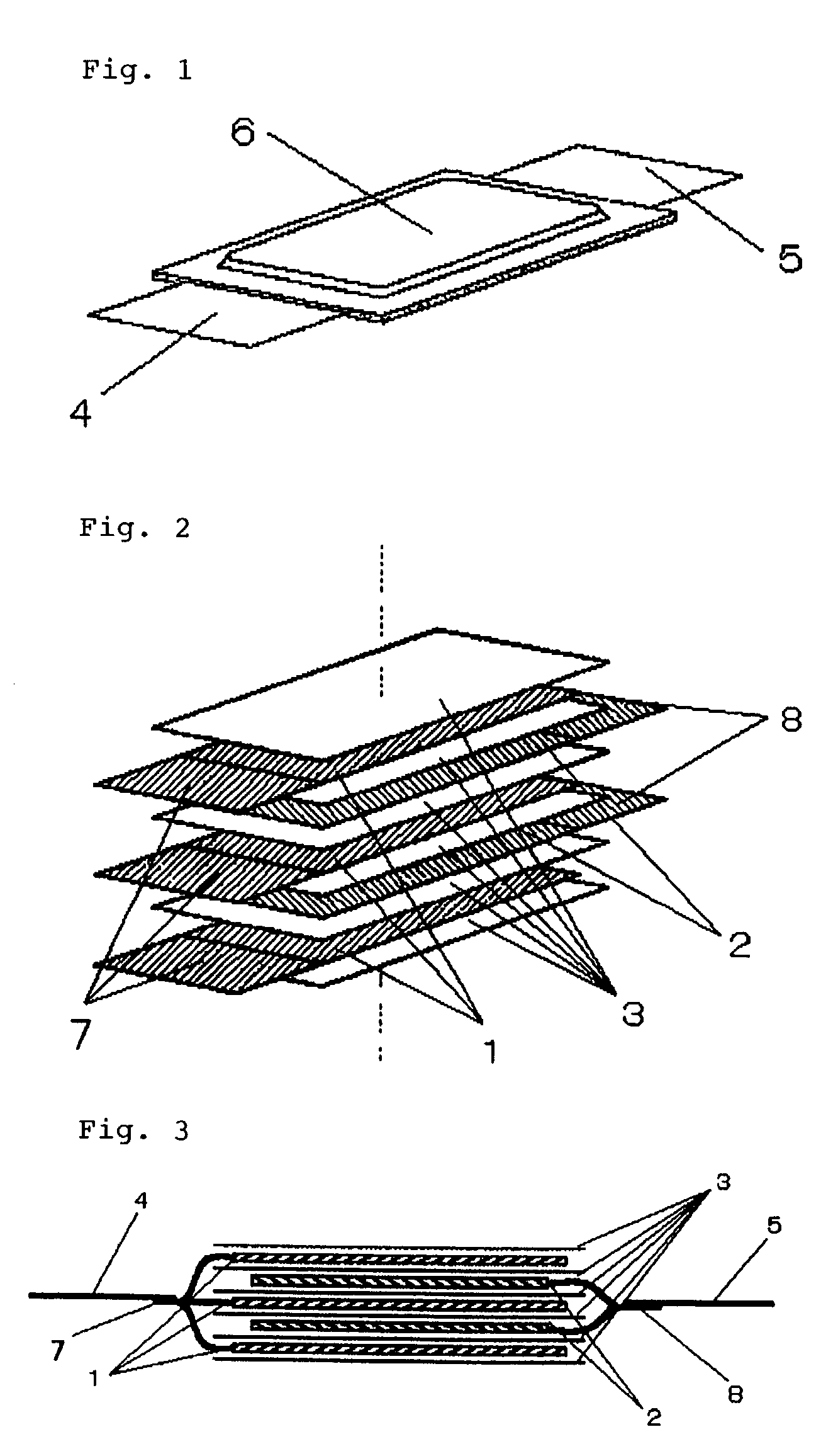
[0066]As shown in FIGS. 2 and 3, there were alternately laminated: negative electrode bodies 1 each of which comprises a copper foil sheet of a 15 μm thickness coated with hard carbon at a thickness of about 50 μm on both surfaces; positive electrode bodies 2 each of which comprises an aluminum foil sheet of a 20 μm thickness coated with lithium-manganese complex oxide at a thickness of about 70 μm on both surfaces; and laminated type separators 3 each of which comprises an insulative porous resin thin-film sheet of a 25 μm thickness which is in itself constituted by laminating polyethylene films and polypropylene films. As shown in FIG. 3, the negative electrode collecting portions 7 and positive electrode collecting portions 8 were taken out in a manner not overlapping with the laminated electrical energy generating bodies, and the negative electrode collecting portions 7 and positive elect...

example 2

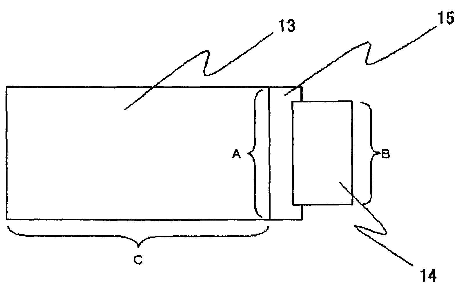
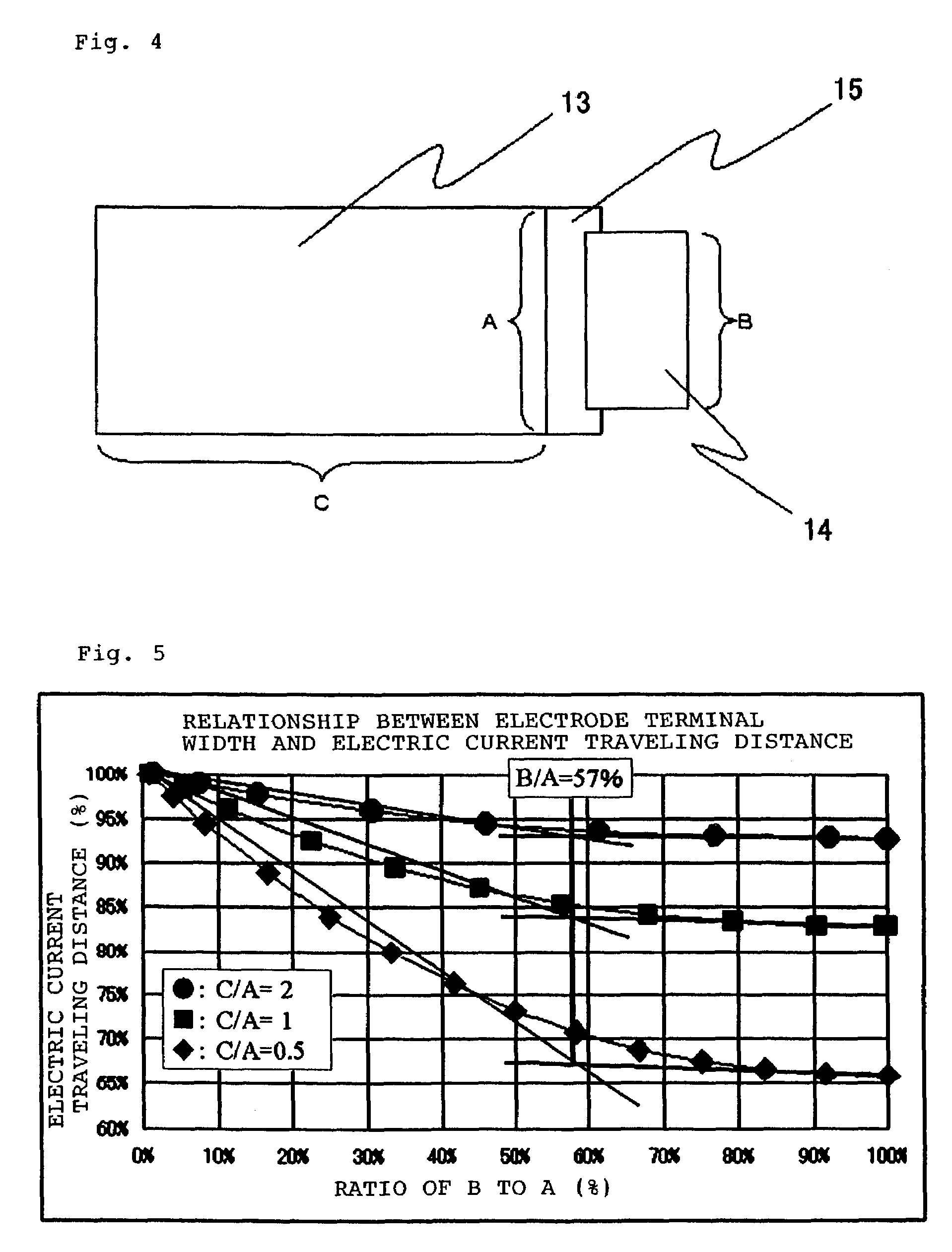
[0067]This EXAMPLE had the same constitution as EXAMPLE 1, except that the width of each of negative electrode terminal 4 and positive electrode terminal 5 was 50 mm. Thus, the values of B / A of the negative electrode and positive electrode were 0.71 and 0.77, respectively.

example 3

[0075]FIG. 8a shows a combined battery constituted by fabricating 3 each of two parallel connected cells, and by thereafter series connecting these cells. This shall be called a “3-series 2-parallel” type, and there shall be called a “Y-series X-parallel” type in case of series connecting Y parts of parallel connected X cells.

[0076]Firstly, there were prepared 3 each of 2-parallel-connection units, each consisting of stacked two cells, then the negative electrode collecting portions 7 and positive electrode collecting portions 8 of pertinent parallel-connection units were mutually connected by such as ultrasonic welding, spot welding or calking. Although there are provided collecting-portion connecting portions 9 for better understanding in FIG. 8a, these portions are the ones connected by welding or calking. The parallel-connection units were eventually stacked in 3 folds as shown in FIG. 8a, thereby obtaining a combined battery of a 3-series 2-parallel / collecting terminal double-s...


PUM


Abstract

The battery is constituted to satisfy B/A≧0.57, wherein “A” represents a width of an active material region and “B” represents a width of each electrode terminal.

Description

BACKGROUND OF THE INVENTION[0001]1. Field of the Invention[0002]The present invention relates to a flat-type cell and a combined battery utilizing the same.[0003]2. Description of the Prior Art[0004]Conventionally, there have been adopted battery cans made of metal as packages of batteries, while adjusting the sizes of cans into shapes of a cylinder, a rectangle and a coin corresponding to the usage. Recently, particularly in the field of portable equipment which is thin and light-weight, there has been a strong demand to attain a thin and light-weigh battery as a power source corresponding to such portable equipment.[0005]Since those batteries adopting battery cans made of metal have a limitation on how thin and light-weight they can be, recent investigation have been conducted to develop batteries adopting packages constituted by thermally sealing a laminated film comprising laminated resin films and metal films, to thereby produce a film armored battery which is remarkably light-...

Claims


Application Information

Patent Timeline
IPC IPC(8): H01M2/26H01M2/02H01M2/08H01M6/42H01M6/46H01M10/00H01M10/04H01M10/05H01M10/058H01M50/119H01M50/121H01M50/124H01M50/176H01M50/50H01M50/548H01M50/553H01M50/562
CPCH01M2/0275H01M2/0285H01M2/20H01M2/30H01M10/0436H01M2/266H01M10/052H01M6/42Y02E60/10H01M50/50Y02P70/50H01M50/562H01M50/121H01M50/124H01M50/553H01M50/176H01M50/548H01M50/119
Inventor KANETA, HIROSHI
Owner NEC CORP
Why Eureka
Try Eureka