Catadioptric system and exposure device having this system

Inactive Publication Date: 2006-04-18
NIKON CORP
View PDF33 Cites 61 Cited by
  • Summary
  • Abstract
  • Description
  • Claims
  • Application Information

AI Technical Summary

Benefits of technology

[0014]An object of the present invention, which has been achieved by addressing the problems discussed above, is to provide a catadioptric system that facilitates adjustment and high precisio

Problems solved by technology

However, since light absorption becomes a factor that needs to be taken into consideration, only limited types of optical glass can be utilized in practical application in conjunction with exposure light with small wavelengths.
In such a situation, if the projection optical system is constituted by using refractive optical members (lenses, plane parallel plates, etc.) alone, it is impossible to correct any chromatic aberration with the refractive projection optical system.
In other words, it is extremely difficult to constitute a projection optical system achieving the required resolution with refractive optical members alone.
However, the reflective projection optical system achieved by using reflective optical members alone is bound to become large.
It is to be noted that it is extremely difficult to form a high precision aspherical reflecting surface in the actual manufacturing process.
However, a sufficient working distance cannot be readily assured in the vicinity of the first plane in the symmetrical optical system for reciprocal paths.
As a result, it is difficult to miniaturize the concave reflecting mirror whose diameter tends to be necessarily large.
However, the following problems must be addressed with regard to such catadioptric systems.
In the catadioptric system having the optical system portion for reciprocal paths adopting the structure described above provided toward the second plane on the reduction side, other restrictions imposed with regard to the reduction factor make it impossible to assure a sufficiently long distance to the second plane (the wafer surface) over which the light travels after it is reflected at the reflecting mirror.
For this reason, a large number of lenses cannot be inserted in this optical path and the level of brightness achieved at the optical system is bound to be limited.
In addition, even if an optical system with a large numerical aperture is achieved, numerous refractive optical members must be provided in the optical path with a limited length, a

Method used


Image

  • Catadioptric system and exposure device having this system
  • Catadioptric system and exposure device having this system
  • Catadioptric system and exposure device having this system

Examples


embodiments

[0076](Embodiments)

[0077]The following is an explanation of embodiments of the present invention, given in reference to the attached drawings.

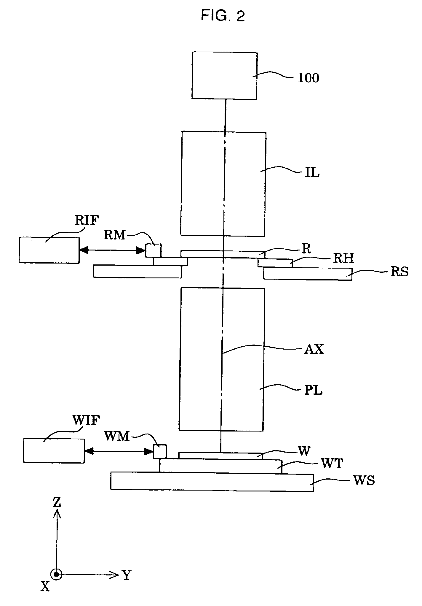
[0078]FIG. 2 schematically illustrates the overall structure of an exposure apparatus having the catadioptric system achieved in any of the embodiments of the present invention as its projection optical system. It is to be noted that in FIG. 2, the Z axis is set parallel to a reference optical axis AX of the catadioptric system constituting a projection optical system PL, the Y axis is set parallel to the drawing sheet of FIG. 2 and the X axis is set perpendicular to the drawing sheet within a plane perpendicular to the optical axis AX.

[0079]The exposure apparatus in the figure includes a light source 100 constituted of an F2 laser light source (with an oscillation central wavelength of 157.6 nm) to supply illuminating light in the ultraviolet range. Light emitted from the light source 100 uniformly illuminates the reticle (mask) R having a sp...

sixth embodiment

[0082]FIG. 3 shows the positional relationships between the rectangular exposure area (i.e., the effective exposure area) formed on the wafer and the reference optical axis. As shown in FIG. 3, a rectangular effective exposure area ER in a desired size is set at a position off the reference optical axis AX along the −Y direction within a circular area (image circle) IF with a radius A (which corresponds to the maximum image height) centered around the reference optical axis AX in all the embodiments except for the The effective exposure area ER measures LX along the X direction and measures LY along the Y direction.

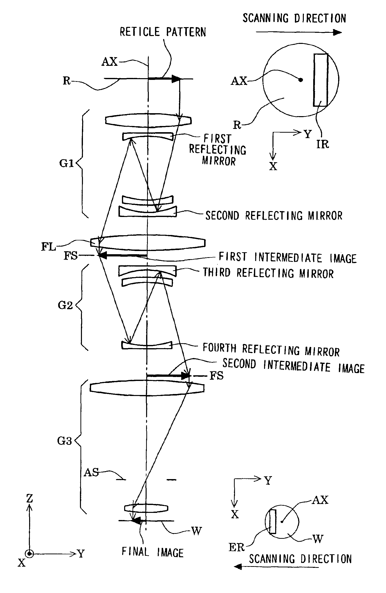
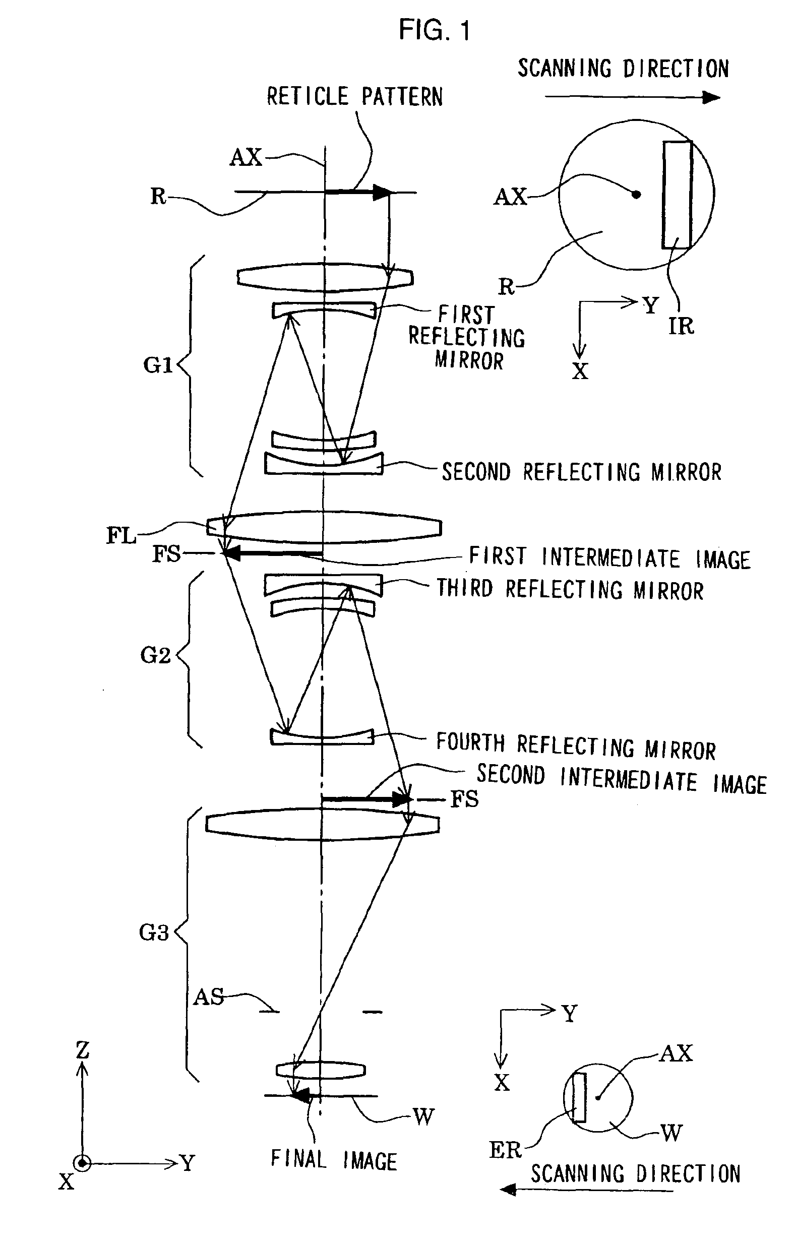
[0083]Thus, the rectangular illumination area IR with a size and shape corresponding to those of the effective exposure area ER is formed on the reticle R at a position off the reference optical axis AX along the +Y direction as shown in FIG. 1. Namely, the rectangular illumination area IR with a desired size is set at a position off the reference optical axis AX along t...

first embodiment

[0094](First Embodiment)

[0095]FIG. 4 shows the lens configuration adopted in the catadioptric system (projection optical system PL) in the first embodiment. In the catadioptric system in FIG. 4, the first image forming optical system G1 is constituted with, starting on the reticle side, a positive meniscus lens L11 having an aspherical convex surface set facing toward the wafer, a positive meniscus lens L12 having an aspherical convex surface set facing toward the wafer, a concave reflecting mirror M11 having an almost flat concave surface set facing toward the wafer, a negative meniscus lens L13 having a concave surface set facing toward the reticle and a concave reflecting mirror M12 having a concave surface set facing toward the reticle.

[0096]In addition, the second image forming optical system G2 is constituted with, starting on the reticle side, a concave reflecting mirror M21 having a concave surface set facing toward the wafer, a negative meniscus lens L21 having a convex sur...


PUM


Abstract

A catadioptric system includes: a first image forming optical system that includes at least two reflecting mirrors and forms a first intermediate image of a first plane with light originating from the first plane; a second image forming optical system that includes at least two reflecting mirrors and forms a second intermediate image of the first plane with light having traveled via the first image forming optical system; and a refractive type of third image forming optical system that forms a final image of the first plane onto a second plane with light having traveled via the second image forming optical system, and optical members constituting the first image forming optical system, the second image forming optical system and the third image forming optical system are all disposed along a single linear optical axis.

Description

[0001]The disclosures of the following priority applications are herein incorporated by reference: Japanese Patent Application No. 2000-322068 filed Oct. 23, 2000; Japanese Patent Application No. 2001-003200 filed Jan. 11, 2001; and Japanese Patent Application No. 2001-309516 filed Oct. 5, 2001.TECHNICAL FIELD[0002]The present invention relates to a catadioptric system and an exposure apparatus having this catadioptric system and, more specifically, it relates to a high resolution catadioptric type projection optical system ideal in an application in an exposure apparatus which is employed when manufacturing semiconductor elements or the like through a photolithography process.BACKGROUND ART[0003]As further miniaturization is pursued with increasing vigor in the field of semiconductor production and semiconductor chip substrate production today, the projection optical system in an exposure apparatus that prints patterns needs to achieve higher resolution. The wavelength of the expos...

Claims


Application Information

Patent Timeline
IPC IPC(8): G03B27/54G02B17/00G02B13/18G02B13/22G02B17/08G03F7/20G03F7/22H01L21/027
CPCG02B17/0844G03F7/70275G03F7/70225G02B17/0892H01L21/027
Inventor TAKAHASHI, TOMOWAKI
Owner NIKON CORP
Why Eureka
Try Eureka