Method and apparatus for generating a composite signal

a composite signal and signal technology, applied in the direction of generating/distributing signals, phase-modulated carrier systems, instruments, etc., can solve the problems of power-inefficient mechanization, constant-envelope signal structure, amplitude fluctuations of 4–5 db peak-to-average power, etc., to improve reliability and power efficiency, simplify hardware implementation, and reduce cost, weight, size and complexity

Active Publication Date: 2006-05-02
HARRIS CORP
View PDF2 Cites 20 Cited by
  • Summary
  • Abstract
  • Description
  • Claims
  • Application Information

AI Technical Summary

Benefits of technology

[0019]Therefore, in light of the above, and for other reasons that become apparent when the invention is fully described, an object of the present invention is to simplify the hardware implementation of a programmable waveform generator, thereby to improve reliability and power efficiency, to reduce cost, weight, size and complexity, and to make the programmable waveform generator easier to adjust during manufacture and in field operation.
[0020]A further object of the invention is to efficiently generate a constant-envelope signal to allow use of saturated high power amplifiers in signal transmission.
[0021]Yet a further object of the present invention is to apply high data rate amplitude and phase modulation to an ultra high frequency or microwave CW carrier without introducing excessive amplitude or phase distortion, thereby making interplex modulation feasible at RF frequencies.
[0025]In accordance with the present invention, a programmable waveform generator requiring fewer components to modulate multiple information signals onto an RF carrier can be realized. An underlying principle of the invention involves the recognition that modulation schemes for transmitting composite signals, such as interplex modulation, can be implemented more efficiently by judiciously mapping the values of the information signals to control of phase modulators and amplitude attenuators responsible for effecting modulation of the RF carrier.
[0027]Advantageously, in contrast to the interplex modulation technique described in the aforementioned patent application, the interplex modulator of the present invention requires less than one-half the modulation hardware, is lighter in weight, smaller, easier to adjust in manufacture, more power efficient and reliable, and costs significantly less. These advantages are particularly advantageous in applications such as space satellites and cellular telephones. Such interplex modulation has commercial application in, for example, GPS signal transmission and in CDMA transmission, as used in wireless telephony.
[0028]While the exemplary embodiment described herein involves an amplitude / phase constellation relating to a particular interplex modulation scheme, the signal modulation technique of the present invention allows instantaneous and simultaneous programmability of amplitude and phase of any modulated carrier point in an amplitude / phase constellation (i.e., the set of desired amplitude and phase points of the modulated carrier) and can be extended to nay of a variety of phase and amplitude modulation schemes.

Problems solved by technology

Linear methods that generate non-constant-envelope composite signals result in power-inefficient mechanizations, because the power amplifiers that are used for transmission of the composite signals must operate in the linear region.
Therefore, constant-envelope signal structures are required if full-power, undistorted transmission is sought.
In addition, the rather severe spectral containment filtering applied to each user signal before multiplexing creates amplitude fluctuations of 4–5 dB peak-to-average power, requiring additional backoff.
Thus, linear combination techniques are maximally efficient in the sense that there is no actual signal power loss, but the overall efficiency of such techniques is compromised by the need to operate the amplifier at a significant power back-off to accommodate the instantaneous signal envelope fluctuations.
Further, conventional PSK / PM systems have limited power efficiency, because PSK / PM systems include unmodulated carrier and cross modulation terms, which represent wasted power.
Applied to orthogonal waveforms, non-linear multiplex methods that produce a composite constant-envelope signal permit a greater fraction of the available transmitter power to be used for communication, but at the expense of a multiplexing loss that may be characterized as either cross-talk (induced non-orthogonality or harmonic distortion) or receiver cross-correlation mismatch.
This multiplexing loss, however, is typically smaller than the power backoff it replaces, resulting in a favorable trade.
The conventional interplex modulation scheme shown in FIG. 1 suffers from a variety of limitations.
While this architecture can be used in certain communication systems, such an approach is not suitable for microwave systems, such as GPS, because the baseband frequency is too low to preclude harmonic and intermodulation interference with the desired microwave output.
Moreover, timejitter in required digital-to-analog converters adds phase noise onto the desired output signal.
Further, in the up-conversion process, the bandpass filters required for each mixing stage produce ringing at phase transitions that generate amplitude envelope variations, which interfere with the efficiency of the saturated high-power amplifiers required for low-power consumption.
A result of this non-constant-envelope is signal distortion that adversely impact Bit Error Rate in CDMA systems and navigation accuracy in GPS applications.
However, the particular interplex modulator implementations described in the aforementioned patent application require a significant number of hardware components.
These components contribute significantly to the overall cost, weight, size and complexity of the system, all of which are of concern in space satellite and commercial CDMA applications such as wireless telephony.
Thus, previous methods of imparting amplitude and phase modulation on an RF carrier are seriously limited by low data rates, low achievable RF frequencies or complex hardware implementations.

Method used


Image

  • Method and apparatus for generating a composite signal
  • Method and apparatus for generating a composite signal
  • Method and apparatus for generating a composite signal

Examples


Embodiment Construction

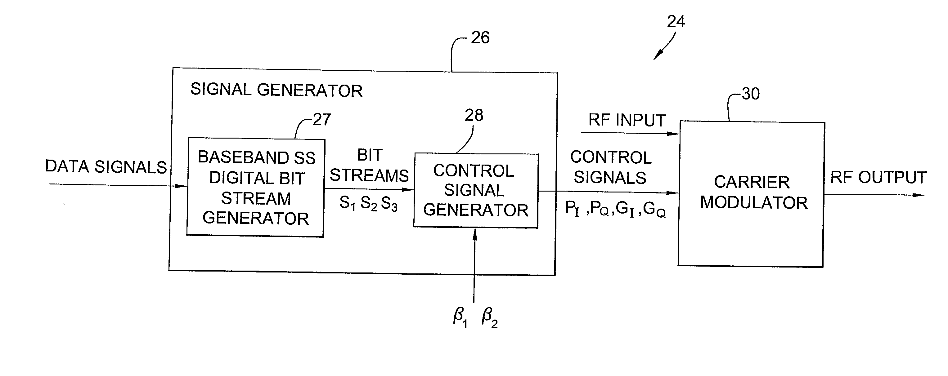
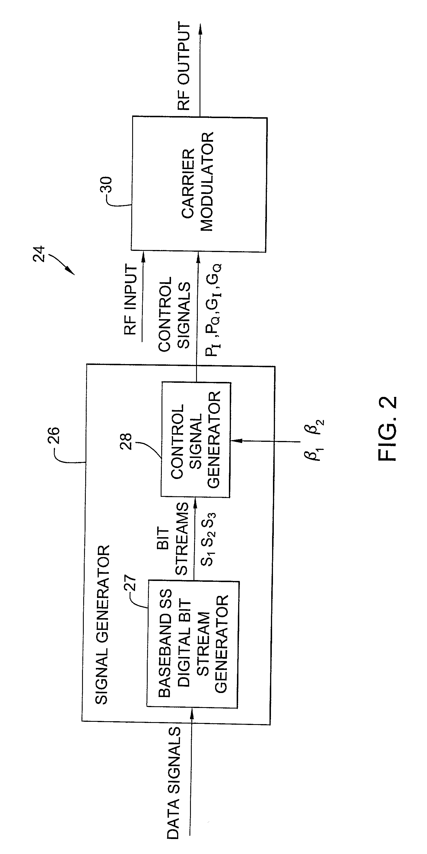
[0034]The following detailed explanations of FIGS. 2–4 and of the preferred embodiments reveal the methods and apparatus of the present invention. In accordance with a non-limiting exemplary embodiment, the waveform generator of the present invention can be employed in a CDMA communication system transmitting multiple CDMA signals to a single location or to group of spatially dispersed users. These signals employ binary phase-shift keying (BPSK) or quadrature phase-shift keying (QPSK), direct sequence (DS) spread spectrum modulation and have a common chip rate and carrier frequency. The timing of the transmissions being under control of the transmitter, the multiple CDMA signals are chip-synchronous. For purposes of illustration, in the exemplary embodiment, three chip-synchronous DS spread-spectrum signals, S1, S2, and S3, are simultaneously transmitted via a constant-envelope composite signal formed using an interplex modulation scheme. However, the present invention is not limite...


PUM


Abstract

A programmable waveform generator forms a composite transmission signal containing multiple information signals using a reduced number of hardware components to modulate the phase and amplitude of the carrier signal. A signal generator develops baseband direct sequence spread spectrum digital bit streams from corresponding input data signals. The values of the digital bit steams are used to simultaneously control states of phase modulators and variable attenuators which modulate the phase and amplitude of the in-phase and quadrature carrier components. The programmable waveform generator can be used to implement an interplex modulator producing a constant-envelope composite signal with fewer phase modulators and attenuators.

Description

BACKGROUND OF THE INVENTION[0001]1. Field of the Invention[0002]The present invention relates to a method and apparatus for generating a composite signal and, more particularly, to a programmable waveform generator operable as an interplex modulator to produce composite, constant-envelope signals.[0003]2. Description of the Related Art[0004]Combining multiple signals on the same radio frequency (RF) carrier is often desirable in both one-way and two-way communications systems, and the importance of signal combining techniques will grow as RF communications systems continue to proliferate and RF spectrum becomes increasingly crowded. Existing methods of signal combining include techniques that generate composite signals whose instantaneous power varies with time (non-constant-envelope signals), such as linear signal combination. Other existing techniques, such as conventional phase shift keyed / phase modulated (PSK / PM) systems, generate constant-envelope composite signals.[0005]Linear...

Claims


Application Information

Patent Timeline
Patent Type & Authority Patents(United States)
IPC IPC(8): H04L27/04H04L27/12H04L27/20H04L5/04
CPCH04L5/04
Inventor DRAGONETTI, PHILIP GEORGE
Owner HARRIS CORP
Why Eureka
Try Eureka