Composite carbon fiber material and method of making same

a technology of composite materials and carbon fibers, which is applied in the directions of adhesive processes, weaving, transportation and packaging, etc., can solve the problems of not being suitable for microelectronic applications presently under consideration, and achieve the effect of small thickness and good electrical conductivity

Inactive Publication Date: 2006-05-09
MICRO CONTACTS
View PDF3 Cites 10 Cited by
  • Summary
  • Abstract
  • Description
  • Claims
  • Application Information

AI Technical Summary

Benefits of technology

[0008]Accordingly, it is an object of the present invention to provide an improved carbon fiber composite material that has similar mechanical properties as existing composites but with a smaller thickness, as well as providing good electrical conductivity, and in which the material is a composite formed of carbon fiber materials and elastomeric resin layers.
[0010]A further object of the present invention is to provide a composite carbon fiber material having multiple layers of the carbon fibers that are aligned in a polymeric matrix and adhered together with the multiple layers then being laminated with mats formed of nonwoven carbon fibers, woven fabric or off-axis unidirectional layers, with the exterior surfaces of the mats being coated with a polymeric resin for forming the composite material into a stable structure.
[0011]In accordance with one aspect of the present invention the carbon fibers that are aligned and bound in a polymeric matrix are combined between two nonwoven carbon fiber mats, woven fabric or off-axis unidirectional layers. The nonwoven carbon fiber mats, woven fabric, or off-axis unidirectional layers provide improved mechanical strength and stability to the aligned carbon fiber layer and also provide a primary current carrying capability to aid in the overall electrical conductivity of the composite material. Unidirectional electrical conductivity can be achieved by using two methods: carbon fiber to carbon fiber contact between the individual layers that is applicable to both non-conductive and conductive polymers; and / or by adding conductive materials to the resin layer or layers. The fabrication techniques utilized in making the composite material create a network of connections between the differently oriented carbon fibers to provide the desired electrical conductivity. The extent of this conductivity is regulated by the resin volume fraction and may be increased by introducing conductive particles into the resin layer or layers of the composite.
[0012]The unidirectional carbon fiber layer is used for carrying electrical current along a primary axis as well as creating mechanical stability along that axis. Used alone, however, this material provides no off-axis electrical conductivity and has virtually no off-axis mechanical stability. The present invention teaches the use of a nonwoven fabric, woven fabric and off-axis unidirectional layer of carbon fibers to provide off axis current carrying capabilities, as well as adding off-axis mechanical stability.

Problems solved by technology

Although thin-gauge composite materials exist, they are not suitable for microelectronic applications presently under consideration.

Method used


Image

  • Composite carbon fiber material and method of making same
  • Composite carbon fiber material and method of making same
  • Composite carbon fiber material and method of making same

Examples


Embodiment Construction

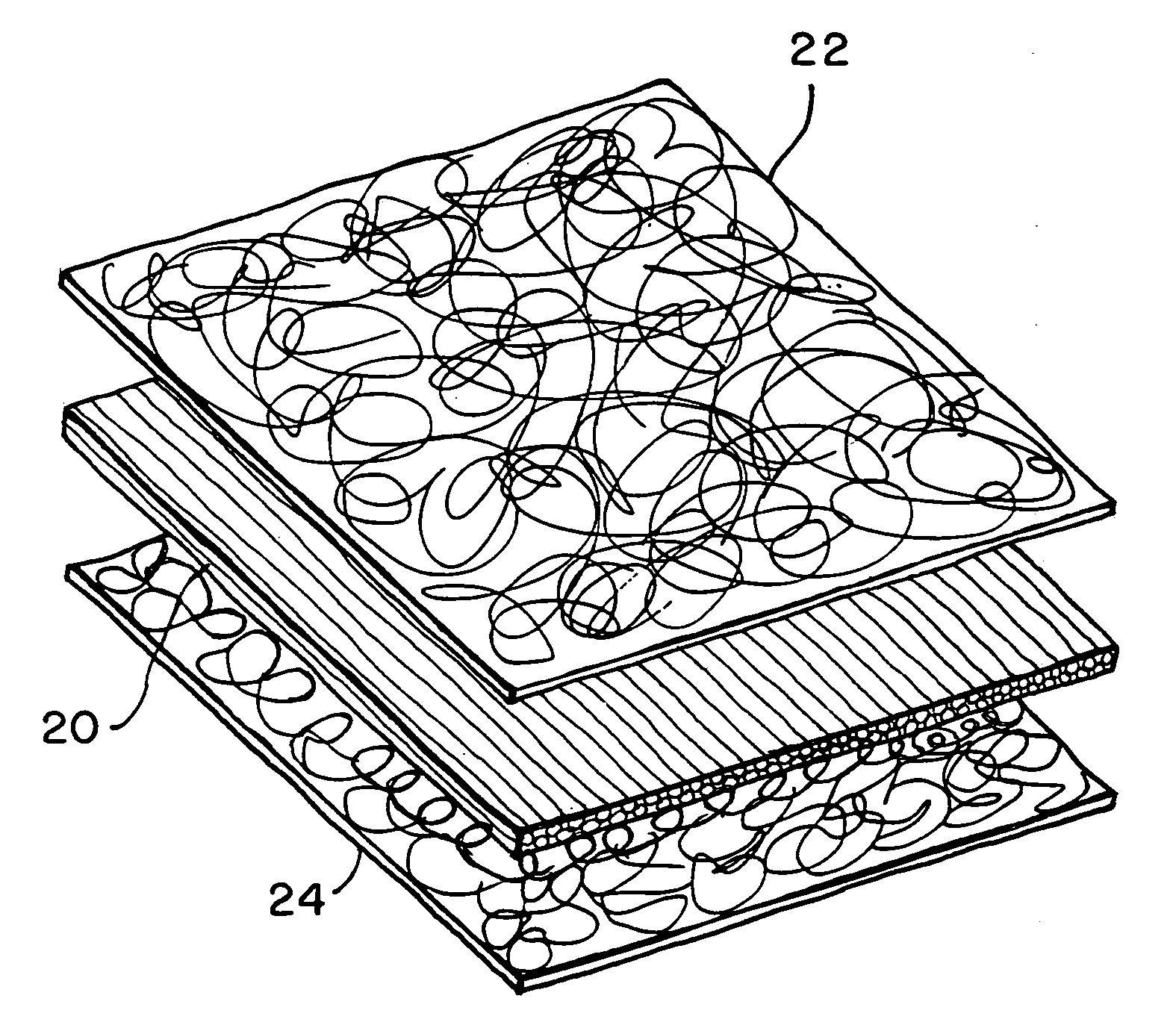
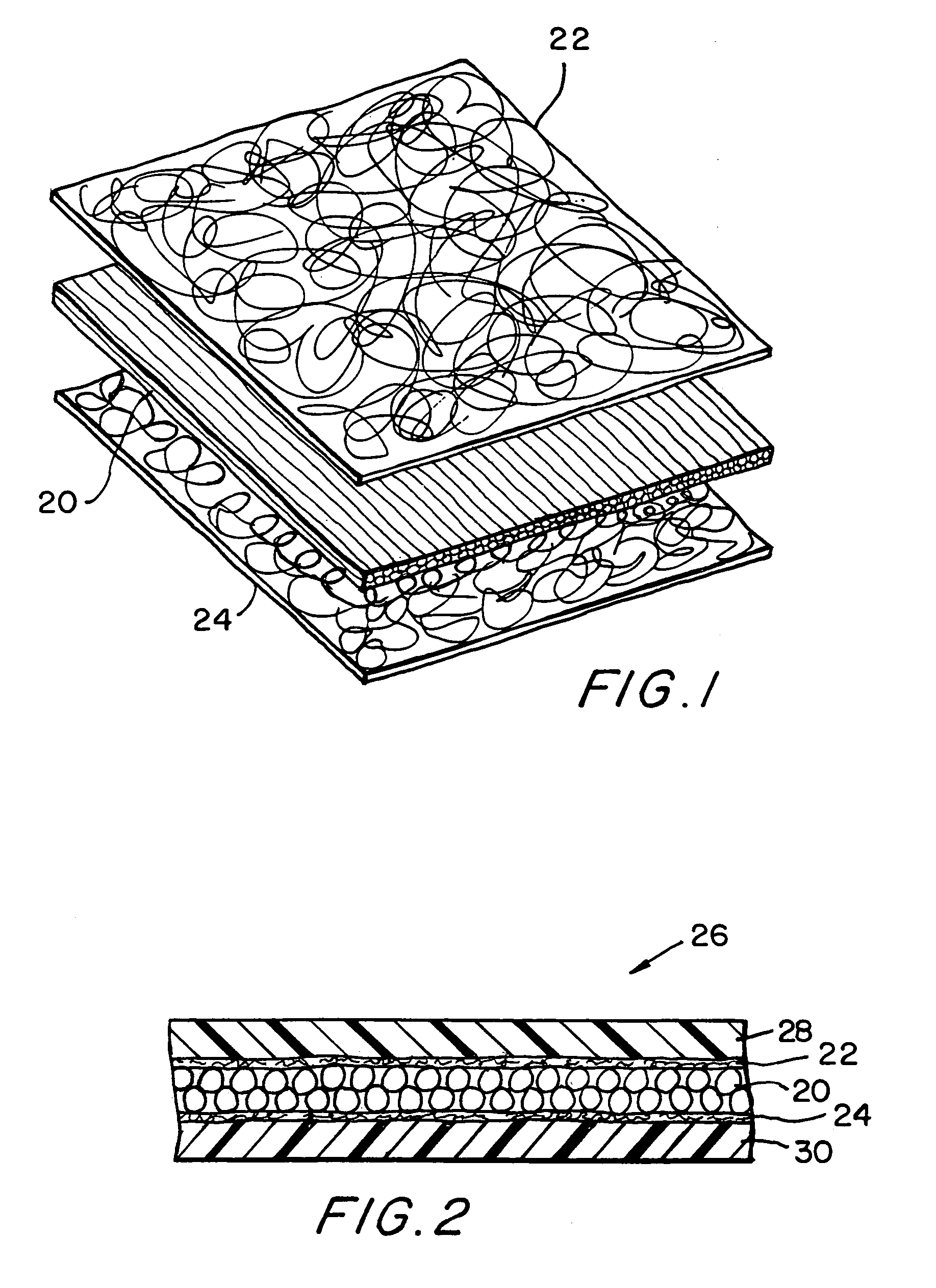
[0022]In FIG. 1 an exploded view of the inventive composite carbon fiber material is shown in which a central layer 20 is formed of aligned carbon fibers that are held together by a plastic matrix. Arranged on either side of the central layer 20 are mats 22 and 24 that are formed of nonwoven carbon. These mats 22, 24 are ultrathin carbon fiber material that is extremely light weight and uniform and is substantially isotropic, because there is almost no directionality of the fibers in the plane of the nonwoven carbon fiber fabric.

[0023]As noted, the nonwoven carbon fiber mat is an ultrathin material and is generally available having a thickness from 0.08 mm to 0.79 mm. In that regard, one commercial source for this nonwoven carbon fiber mat or material is the Hollingsworth & Vose Company, 112 Washington Street, East Walpole, Mass. 02032.

[0024]The composite material is formed as shown in FIG. 2, in which following the arrangement of the mats 22, 24 over the aligned carbon fiber centra...


PUM

PropertyMeasurementUnit
thicknessaaaaaaaaaa
thicknessaaaaaaaaaa
thicknessaaaaaaaaaa

Abstract

A composite carbon fiber material is formed of one or more layers of carbon fiber material in which the carbon fibers are aligned all in the same direction and a mat of nonwoven, woven, or off-axis unidirectional carbon fibers are laminated together. Layers may be used individually or as a hybrid. The layers can be preimpregnated or impregnated during processing using thermoplastic or thermosetting resins. A layer of thermoplastic resin is applied either over the surface or within the composite structure, and the resin permeates the material so as to provide a more stable mechanical structure once the resin is processed. The material combines good mechanical strength with improved electrical current carrying properties when compared with the aligned carbon fiber layer alone. The layering sequence, layer type, and resin type can be specified to tailor electrical properties, mechanical properties, durability, and wear resistance. The resultant material achieves these results in substantially smaller material thickness than previously available.

Description

[0001]This is a division of prior application Ser. No. 09 / 899,782 filed Jul. 5, 2001, now U.S. Pat. No. 6,759,352.BACKGROUND OF THE INVENTION[0002]1. Field of the Invention[0003]This invention relates generally to a thin-gauge composite material formed of layers of specialized carbon fibers and polymeric resins and, more particularly, to a composite carbon fiber material that is useful in an electrical contact assembly typically used in an electromechanical device.[0004]2. Description of the Background[0005]The use of carbon fiber material for structural applications is well known. Typically, this material is composed of multiple layers of either woven fabric or layers of unidirectional, continuous carbon fibers that are laminated together. The orientation and number of layers are chosen to meet the stiffness, strength, and dimensional stability requirements of the particular application. In typical aerospace applications the thin gauge material has between four to eight plies, with...

Claims


Application Information

Patent Timeline
Patent Type & Authority Patents(United States)
IPC IPC(8): C09J5/00C08J5/04B29C70/08B32B5/26B32B5/28B32B9/00C08K7/06C08L101/12D04H1/4242D04H1/4374D04H1/593D04H3/002D04H3/04D04H3/12D04H13/00
CPCB29C70/083B32B5/28B32B9/00D04H13/002Y10T428/24132Y10T428/24124Y10T428/24099D04H1/4242D04H1/4374D04H1/593D04H3/002D04H3/04Y10T428/249945Y10T442/2041Y10T442/643Y10T442/60Y10T428/24994Y10T442/2049B32B2262/106B32B5/26B32B5/022
Inventor DELANOY, CURTGILLESPIE, JOHN
Owner MICRO CONTACTS
Why Eureka
Try Eureka