Stepped reflector plate

a reflector plate and step technology, applied in the field of material thermal processing apparatus and methods, can solve the problems of difficult measurement, inability to measure, and inability to introduce unknown errors into temperature measurements, so as to improve the performance of the pyrometer, promote rapid cooling of the substrate, and reduce the effect of reflectivity

Inactive Publication Date: 2006-05-09
APPLIED MATERIALS INC
View PDF13 Cites 36 Cited by
  • Summary
  • Abstract
  • Description
  • Claims
  • Application Information

AI Technical Summary

Benefits of technology

[0010]The present invention is generally directed to a method and apparatus for thermally processing a substrate. Generally, a reflector has a stepped surface including a number of recesses. Pyrometers are coupled to the recesses, and the surface of the reflector in the recesses is highly reflective to optimize the performance of the pyrometers. Other portions of the reflector surface have reduced reflectivity, to promote rapid cooling of the substrate. The stepped surface also reduces the volume of purge gas needed to fill the process chamber.

Problems solved by technology

However, optical pyrometry suffers from limitations due to the inability to accurately measure the emissivity of a substrate.
These changes are difficult to measure and therefore introduce an unknown error into the temperature measurements.
Nevertheless, some error is necessarily introduced because the reflector is not an ideal reflector, and so the light received by the pyrometer is not perfectly representative of the light emitted by the substrate.
These methods, however, require careful control of the gases, which can complicate and / or prolong the process.

Method used


Image

  • Stepped reflector plate
  • Stepped reflector plate
  • Stepped reflector plate

Examples


Embodiment Construction

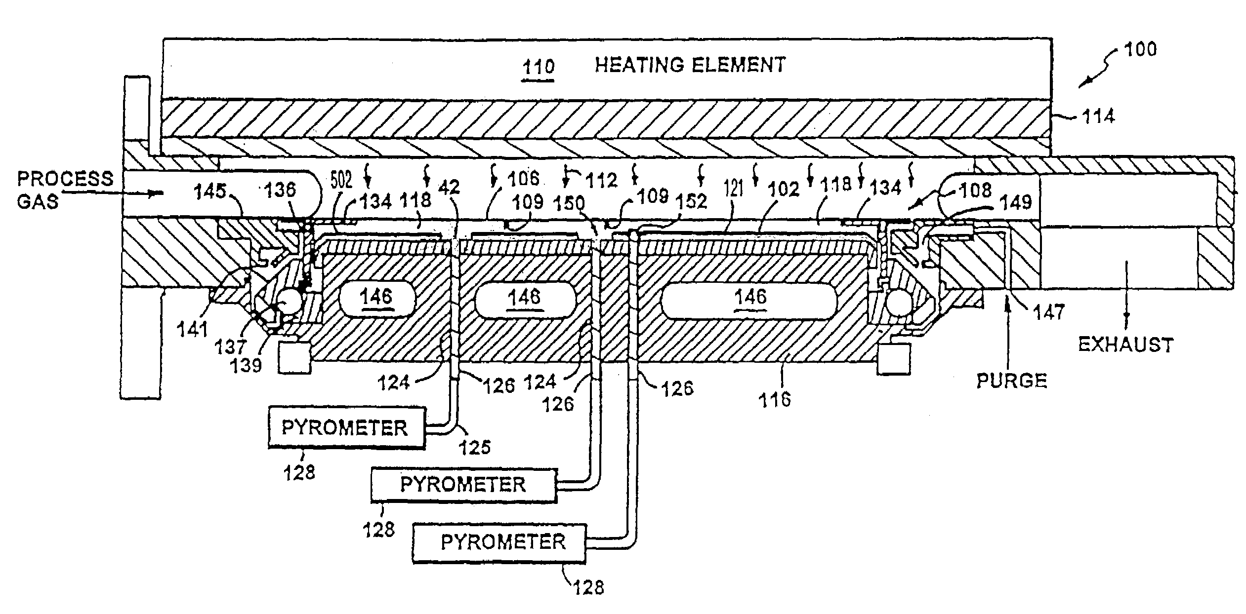
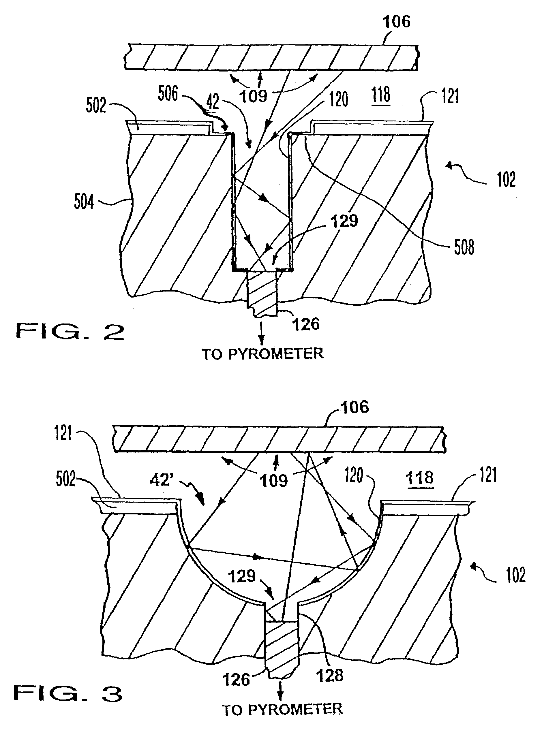
[0023]The present invention is generally directed to a stepped reflector plate for use in thermally processing a substrate. A reflector plate has a stepped surface facing the substrate during heating and cooling of the substrate. The raised surface of the reflector plate is non-reflective, providing advantages during, among other things, cooling of the substrate. The reflector plate also includes a number of recesses, in which one or more pyrometers are positioned. These recesses have a reflective surface, providing advantages in the performance of the pyrometers.

[0024]The RTP System

[0025]An RTP system in accordance with one embodiment of the present invention is shown in FIG. 1. The RTP system includes a processing chamber 100 for processing a substrate 106. In one embodiment of the present invention, the substrate 106 is a disk-shaped, eight inch (200 mm) diameter silicon substrate. In another, it is a twelve inch (300 mm) diameter silicon substrate. The substrate 106 is mounted i...


PUM

PropertyMeasurementUnit
reflectivityaaaaaaaaaa
diameteraaaaaaaaaa

Abstract

In a system for thermal processing of a semiconductor substrate, a reflector plate has a stepped surface facing the substrate during heating and cooling of the substrate. The raised surface of the reflector plate has reduced reflectivity, providing advantages during, among other things, cooling of the substrate. The reflector plate also includes a number of recesses to which one or more pyrometers are coupled. These recesses have a highly reflective surface, providing advantages in the performance of the pyrometers.

Description

BACKGROUND OF THE INVENTION[0001]This invention relates to apparatus and methods of thermally processing a material such as a semiconductor substrate.[0002]A number of applications involve thermal processing of semiconductor and other materials which require precise measurement and control of the temperature of the material. For instance, processing of a semiconductor substrate requires precise measurement and control of the temperature over a wide range of temperatures. One example of such processing is rapid thermal processing (RTP), which is used for a number of fabrication processes, including rapid thermal annealing (RTA), rapid thermal cleaning (RTC), rapid thermal chemical vapor deposition (RTCVD), rapid thermal oxidation (RTO), and rapid thermal nitridation (RTN). In the particular application of CMOS gate dielectric formation by RTO or RTN, thickness, growth temperature, and uniformity of the gate dielectrics are critical parameters that influence the overall device perform...

Claims


Application Information

Patent Timeline
Patent Type & Authority Patents(United States)
IPC IPC(8): F27B5/14F27B5/16F27B17/00F27D11/00F27D19/00F27D21/00H01L21/00
CPCF27B5/16F27B17/0025H01L21/67248F27D21/0014H01L21/67115F27D19/00
Inventor JENNINGS, DEANRANISH, JOSEPH M.HAAS, BRIANBALAKRISHNA, AJITRAMAMURTHY, SUNDARHUNTER, AARONYAM, MARK
Owner APPLIED MATERIALS INC
Why Eureka
Try Eureka