Memory sensing circuit and method for low voltage operation

a memory sensing circuit and low-voltage operation technology, applied in static storage, digital storage, instruments, etc., to achieve the effects of high capacity, high-performance non-volatile memory devices, and high density chip integration

Inactive Publication Date: 2006-05-16
SANDISK TECH LLC
View PDF46 Cites 359 Cited by
  • Summary
  • Abstract
  • Description
  • Claims
  • Application Information

AI Technical Summary

Benefits of technology

[0041]These needs for a high capacity and high performance non-volatile memory device are met by having a large page of read / write circuits to read and write a corresponding page of memory cells in parallel. In particular, disturbance effects inherent in high density chip integration are that may introduce errors into reading and programming are either eliminated or minimized.
[0042]Source line bias is an error introduced by a non-zero resistance in the ground loop of the read / write circuits. The error is caused by a voltage drop across the resistance when current flows. According to one aspect of the invention, a method for reducing source line bias is accomplished by read / write circuits with features and techniques for multi-pass sensing. When a page of memory cells are being sensed in parallel, each pass helps to identify and shut down the memory cells with conduction current higher than a given demarcation current value. The identified memory cells are shut down by pulling their associated bit lines to ground.
[0043]In one implementation, the given demarcation current value is higher than the breakpoint current value for a conventional single-pass sensing. Alternatively, the given demarcation current value progressively converges to the breakpoint current value associated with a conventional single-pass sensing. In this way, sensing in subsequent passes will be less affected by source line bias since the total amount of current flow is significantly reduced by eliminating the contributions from the higher current cells.

Problems solved by technology

Source line bias is an error introduced by a non-zero resistance in the ground loop of the read / write circuits.
The error is caused by a voltage drop across the resistance when current flows.

Method used


Image

  • Memory sensing circuit and method for low voltage operation
  • Memory sensing circuit and method for low voltage operation
  • Memory sensing circuit and method for low voltage operation

Examples


Embodiment Construction

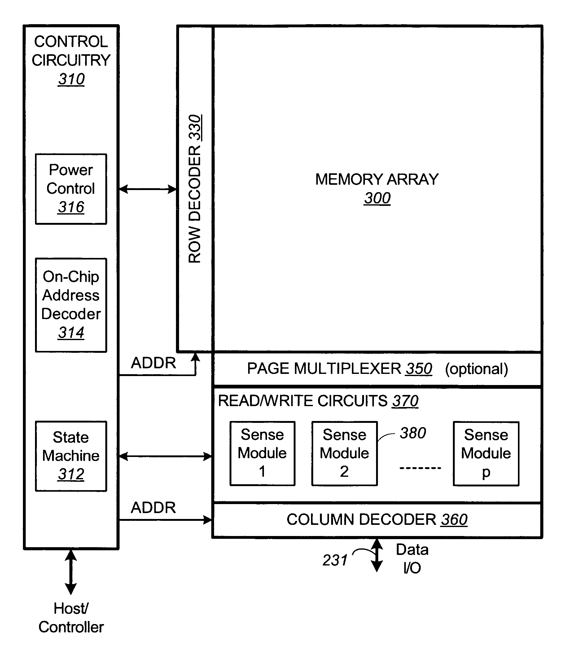
[0091]FIG. 6A illustrates schematically a memory device having read / write circuits for reading and programming a page of memory cells in parallel, according to one embodiment of the present invention. The memory device includes a two-dimensional array of memory cells 300, control circuitry 310, and read / write circuits 370. The memory array 300 is addressable by word lines via a row decoder 330 and by bit lines via a column decoder 360. The read / write circuits 370 include multiple sense modules 380 and allow a page of memory cells to be read or programmed in parallel. In one embodiment, where a row of memory cells are partitioned into multiple pages, a page multiplexer 350 is provided to multiplex the read / write circuits 370 to the individual pages.

[0092]The control circuitry 310 cooperates with the read / write circuits 370 to perform memory operations on the memory array 300. The control circuitry 310 includes a state machine 312, an on-chip address decoder 314 and a power control mo...


PUM


Abstract

A sensing module operates with a sense amplifier sensing a conduction current of a memory cell via a coupled bit line under constant voltage condition in order to minimize bit-line to bit-line coupling. The rate of discharge of a dedicated capacitor as measured by a change in the voltage drop there across in a predetermined period is used to indicate the magnitude of the conduction current. The voltage cannot drop below a minimum level imposed by a circuit for maintaining the constant voltage condition on the bit line. A voltage shifter is used to boost the voltage during the discharge and to unboost the voltage after the discharge, so that the change in voltage drop properly reflects the rate of discharge without running into the minimum level.

Description

CROSS REFERENCE TO RELATED APPLICATIONS[0001]This application is a continuation-in-part of U.S. patent application Ser. No. 10 / 665,828, filed on Sep. 17, 2003, which is a continuation-in-part of U.S. patent application Ser. No. 10 / 254,830, filed on Sep. 24, 2002 now abandoned.FIELD OF THE INVENTION[0002]This invention relates generally to non-volatile semiconductor memory such as electrically erasable programmable read-only memory (EEPROM) and flash EEPROM, and specifically ones having improved sensing circuits that operate with a low voltage supply.BACKGROUND OF THE INVENTION[0003]Solid-state memory capable of nonvolatile storage of charge, particularly in the form of EEPROM and flash EEPROM packaged as a small form factor card, has recently become the storage of choice in a variety of mobile and handheld devices, notably information appliances and consumer electronics products. Unlike RAM (random access memory) that is also solid-state memory, flash memory is non-volatile, retaini...

Claims


Application Information

Patent Timeline
Patent Type & Authority Patents(United States)
IPC IPC(8): G11C7/02G11C7/00G11C7/06G11C11/56G11C16/26G11C16/28
CPCG11C7/062G11C7/067G11C11/5642G11C16/28G11C16/26G11C11/5628G11C16/10G11C2216/22G11C2207/063G11C2211/5621G11C2216/14G11C16/30
Inventor CERNEA, RAUL-ADRIAN
Owner SANDISK TECH LLC
Why Eureka
Try Eureka