Nano-crystalline, homo-metallic, protective coatings

a technology of homo-metallic and nano-crystalline metals, applied in the direction of packaging foodstuffs, shoulder joints, impression caps, etc., can solve the problems of reducing joint mobility and pain, abrasion wear, and limited life of total joint replacement components

Inactive Publication Date: 2006-05-23
N2 BIOMEDICAL
View PDF14 Cites 97 Cited by
  • Summary
  • Abstract
  • Description
  • Claims
  • Application Information

AI Technical Summary

Benefits of technology

[0017]Concurrent with the deposition step, the metallic surface is bombarded with one or more selected ions so as to form a nano-crystalline integral protective coating on the surface, having average grain sizes ranging from about 1 nm to about 999 nm, and having an average atomic concentration of the common constituent element that differs from its average concentration in the metallic surface by less than about 20 percent, and more preferably, by less than about 10 percent. An ion beam, e.g., argon or nitrogen or a mixture of argon and nitrogen, can be directed onto the substrate to assist in the formation of the integral coating.

Problems solved by technology

The lifetime of total joint replacement components is typically limited either by gross failure of the materials of the articulating surfaces (primarily the UHMWPE component) or by biological reactions to debris generated from the wear of the articulating surfaces.
In addition, wear debris can result in the formation of scar tissue which, in turn, can lead to decreased joint mobility and pain.
One such mechanism is abrasive wear which is caused primarily by surface asperities on a hard metallic or ceramic surface in contact with the UHMWPE articulating surface.
However, such ceramic coatings have a number of drawbacks.
For example, it is difficult to achieve adequate adhesion between the metal and the ceramic.
Further, such ceramic coatings are brittle and can render manufacturing of the prosthetic devices which utilize them difficult and costly.

Method used


Image

  • Nano-crystalline, homo-metallic, protective coatings
  • Nano-crystalline, homo-metallic, protective coatings
  • Nano-crystalline, homo-metallic, protective coatings

Examples


example 1

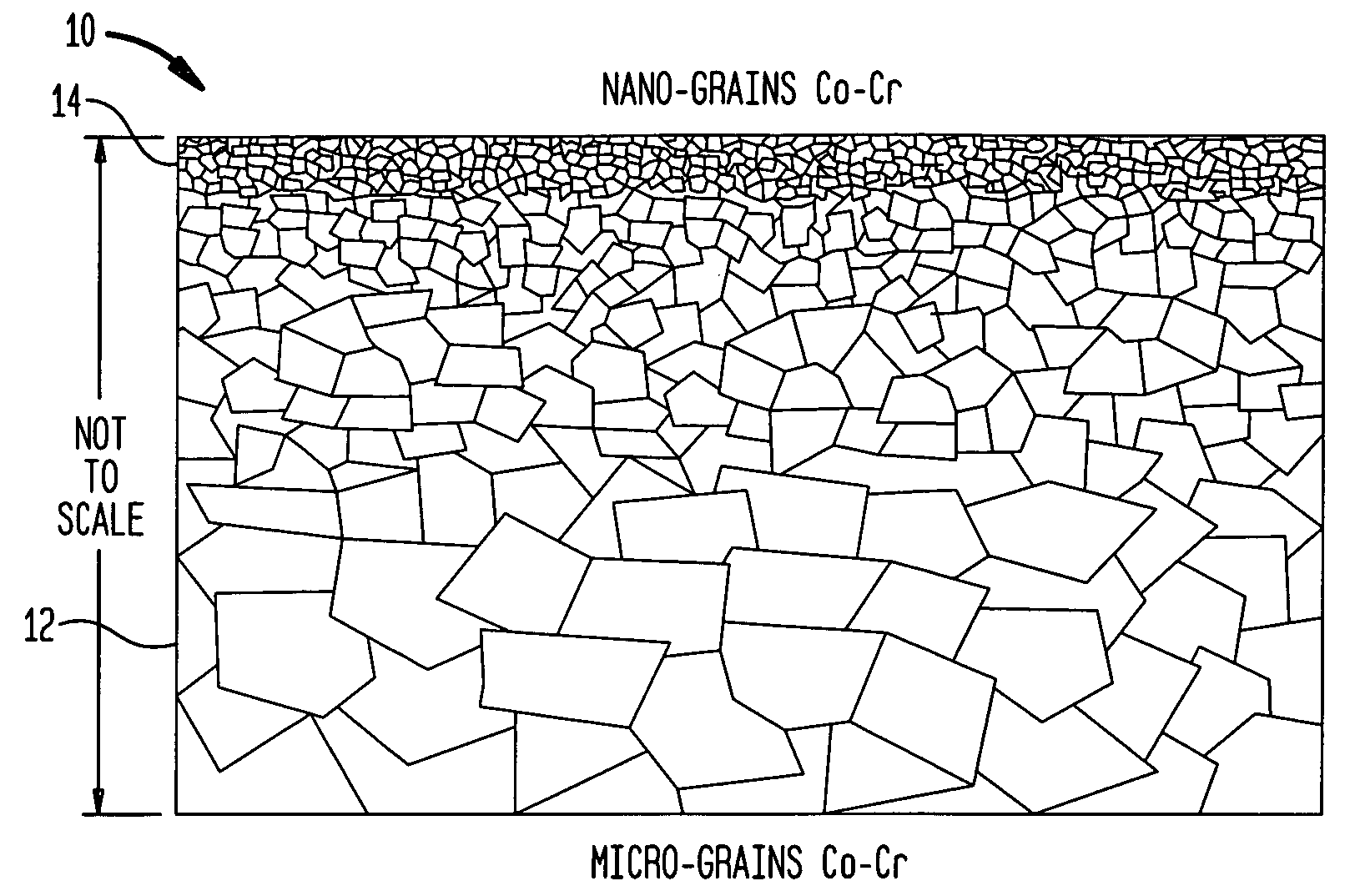
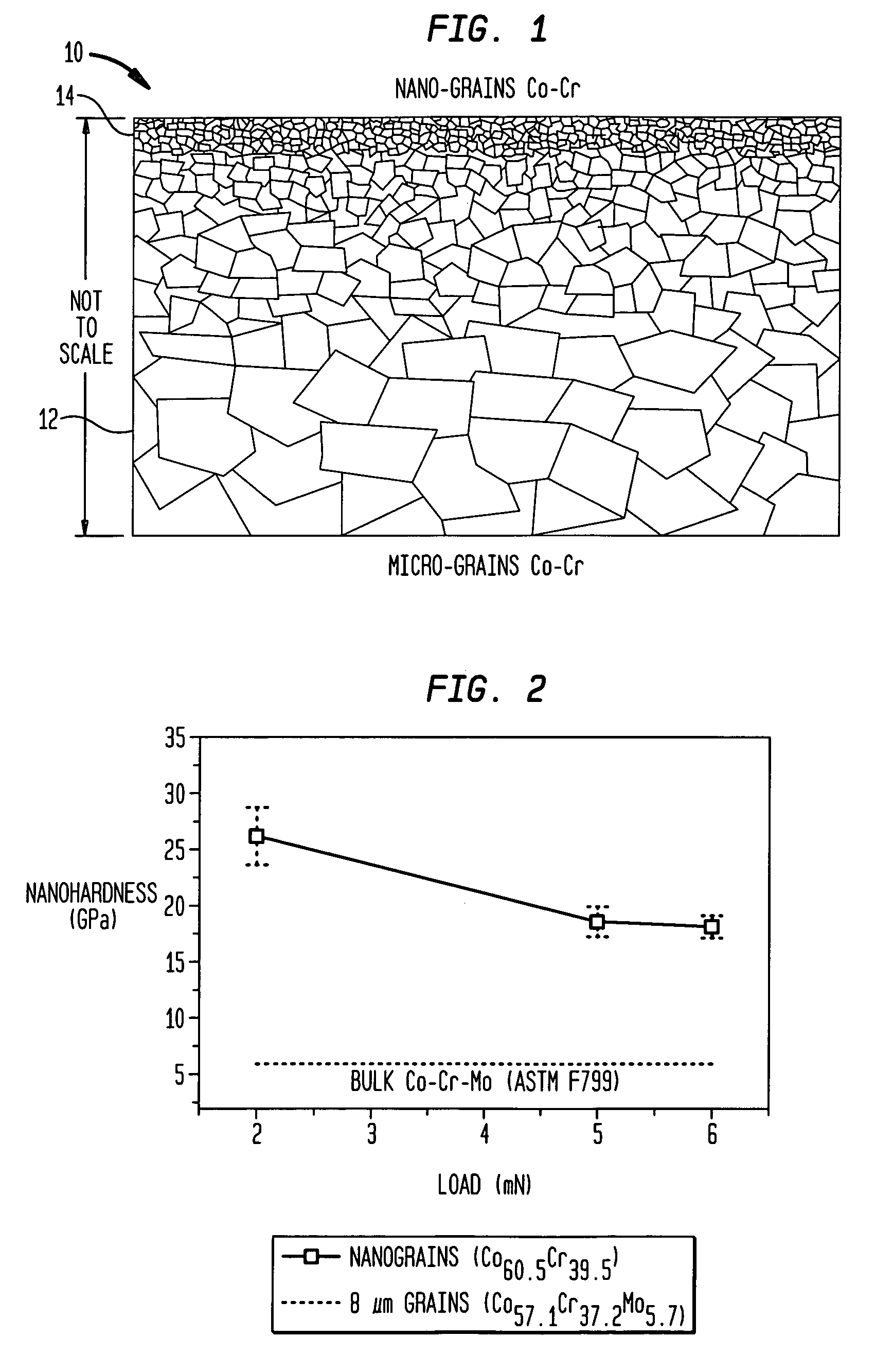
[0054]A plurality of nano-crystalline coatings of Co—Cr was formed on a Co—Cr—Mo substrate (F799 substrate) having an average chemical composition of Co57.12Cr37.2Mo5.7. The chemical composition of the substrate was determined by utilizing Rutherford Backscattering Spectrometry.

[0055]To produce these films, a Co—Cr alloy was evaporated and the evaporated atoms were directed to the surface of the substrate. Concurrently, the substrate was bombarded with a beam of argon ions, having a current density in a range of about 50 to 150 microamperes per square centimeter (μA / cm2) and an ion energy of 500 or 600 eV. The process of simultaneous deposition and ion bombardment of the substrate continued for a selected time period to produce a nano-crystalline film having a desired thickness.

[0056]TEM studies of these Co—Cr coatings show that the grain sizes of the coatings range from about 20 nm to about 40 nm. That is, the coatings include grains having sizes that are a few hundred times smalle...


PUM

PropertyMeasurementUnit
grain sizesaaaaaaaaaa
thicknessaaaaaaaaaa
thicknessaaaaaaaaaa

Abstract

The present invention provides orthopedic prosthesis having at least one metallic component that includes a metallic substrate on which an integrally formed nano-crystalline coating is formed. The coating and the substrate have at least one metallic constituent in common having an average atomic concentration in the coating that differs from an average atomic concentration in the substrate by less than about 10 percent. Further, the nano-crystalline coatings includes crystalline grains with an average size in a range of about 1 to 999 nanometers, and more preferably in a range of about 10 to 200 nanometers. A transition region that exhibits a graded reduction in average grain size separates the coating from the substrate. The coating advantageously exhibits an enhanced hardness, and a high degree of resistance to corrosion and wear. In one application, the nano-crystalline coatings of the invention are utilized to form articulating surfaces of various orthopedic devices.

Description

BACKGROUND[0001]The present invention relates generally to metallic structures having protective coatings and methods for producing such structures. More particularly, the invention provides metallic components for incorporation in orthopedic prosthesis which include surfaces having integrally formed protective coatings that exhibit a high degree of hardness, wear and corrosion resistance.[0002]Metallic structures are utilized in a variety of devices. For example, many prosthetic devices include metallic components. In particular, prosthetic joints, utilized in total joint arthroplasty (TJA) procedures to restore mobility in patients with reduced joint function, typically include two mating and articulating surfaces, one of which is formed of a metal alloy such as titanium-aluminum-vanadium or cobalt-chromium-molybdenum, and the other is formed and / or lined with a plastic component, such as ultrahigh molecular weight polyethylene (UHMWPE).[0003]The recent trends in performing arthro...

Claims


Application Information

Patent Timeline
Patent Type & Authority Patents(United States)
IPC IPC(8): A61F2/28A61F2/00A61F2/30A61F2/32A61F2/34A61F2/36A61F2/38A61F2/40A61L27/04A61L27/30C23C8/02C23C8/36C23C14/16C23C14/22C23C26/00
CPCA61F2/30767C23C26/00A61L27/04A61L27/30C23C8/02C23C8/36C23C14/16C23C14/22A61F2/34A61F2/36A61F2/38A61F2/3804A61F2/3859A61F2/389A61F2/40A61F2002/30004A61F2002/30006A61F2002/30016A61F2002/30051A61F2002/30084A61F2002/30685A61F2002/30878A61F2002/30892A61F2002/30922A61F2002/30929A61F2002/30934A61F2002/3098A61F2002/3611A61F2002/3625A61F2250/0014A61F2250/0015A61F2250/0018A61F2250/0019A61F2250/0054A61F2310/00023A61F2310/00029A61F2310/00407A61F2310/00413A61F2/32A61F2/3094
Inventor NAMAVAR, FEREYDOON
Owner N2 BIOMEDICAL
Why Eureka
Try Eureka