Ultrafiltration membrane, device, bioartificial organ, and methods

a bioartificial organ and ultrafiltration membrane technology, applied in the field of ultrafiltration, can solve the problems of severely hampered electrochemical sensors for glucose measurement, and achieve the effect of controlling ultrafiltration and preventing protein fouling

Active Publication Date: 2006-05-23
RGT UNIV OF MICHIGAN +1
View PDF32 Cites 49 Cited by
  • Summary
  • Abstract
  • Description
  • Claims
  • Application Information

AI Technical Summary

Benefits of technology

[0008]The present invention addresses the unmet needs by providing, in some embodiments, systems and methods for filtering fluids in vivo and in vitro. In some embodiments, the present invention provides devices having membranes containing precisely configured pores that permit very controlled ultrafil

Problems solved by technology

Present electrochemical sensors for glucose measurement are severely hampered by protein fouling of t

Method used


Image

  • Ultrafiltration membrane, device, bioartificial organ, and methods
  • Ultrafiltration membrane, device, bioartificial organ, and methods
  • Ultrafiltration membrane, device, bioartificial organ, and methods

Examples


example 1

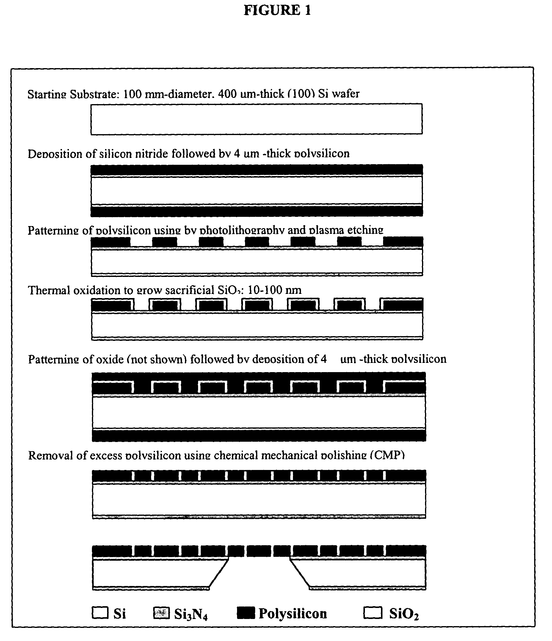
Nanofabrication of Membranes

[0128]This example describes the process flow for fabrication of nanomembranes; this process is depicted in FIG. 1. The starting substrate is a 400 μm-thick, 100 mm-diameter, double side polished (100)-oriented silicon wafer that is obtained from a commercial vendor of semiconductor substrates. The wafer is coated with a 5000 Å-thick layer of low-stress silicon nitride (LSN) by low-pressure chemical vapor deposition (LPCVD). Next, a 4 μm-thick film of polysilicon is deposited by LPCVD and followed by thermal oxidation to grow a 2500 Å-thick layer of SiO2. The oxide layer on the wafer front side is then patterned by photolithography and wet etching in buffered hydrofluoric acid (BHF) to create an etch mask, which is used to pattern the underlying polysilicon film by reactive ion etching (RIE) in chlorine plasma. Afterwards, BHF is used to remove the masking oxide on both wafer front and back sides and followed by RIE to remove polysilicon on the wafer back...

example 2

Extracorporeal Hemofiltration

[0129]This example demonstrates how a nanofabricated nanoporous membrane may be used to form an extracorporeal hemofiltration device (see e.g., FIG. 3). Blood from a patient or from a stored supply is directed to an orifice 600 by means of a cannula, catheter or other means. An optional pump 100, which may be peristaltic, rotary, roller, or other, is used to regulate a flow of blood to a chamber 700, which contains a pressure sensor 401 and is bounded by a membrane 201 composed of a plurality of pores. Said pores may be shaped to optimize hydraulic permeability, and may be all alike or dissimilar. Furthermore, said pores may contain or comprise electrodes, surface treatments, or be coated with chemicals, polymers, proteins, sugars, and the like to impart a particular electrostatic charge to the pore or a region around the pore, and impart an electric field within the pore. Blood exits the chamber 701 via an orifice 602 with an optional pump 102 which may...

example 3

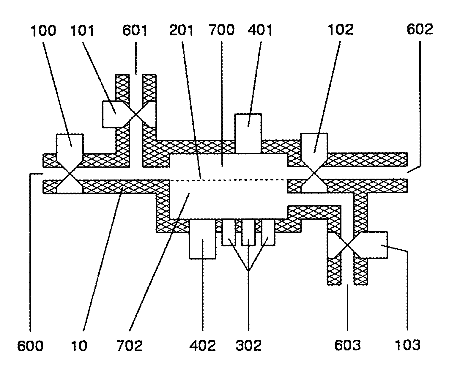
Continuous Blood Glucose Sensor

[0130]This example demonstrates how a membrane may be used to form a continuous blood glucose sensor. The novelty and advantage of this approach is the rapidity with which the glucose level in the blood is transmitted to the sensor, as glucose is carried by convection to the sensor, rather than by diffusion towards the sensor, while still affording the sensor protection from elements in the blood that may be injurious to or degrade the sensor. The example of a blood glucose sensor is not to be construed as limiting the application; it may be applied to the analysis of cell and / or protein free fluids for arbitrary analytes by arbitrary means. A preferred embodiment is illustrated in FIG. 4. Blood from the patient is directed by means of a cannula, a vascular anastamosis, a synthetic graft, or other means to an inlet 600 optionally equipped with a pump or valve or other flow controller 100 to a chamber 700, which optionally contains a pressure sensor 401...


PUM

PropertyMeasurementUnit
Lengthaaaaaaaaaa
Lengthaaaaaaaaaa
Lengthaaaaaaaaaa

Abstract

The present invention relates to ultrafiltration. In particular, the present invention provides a compact ultrafiltration device and methods for generating an ultrafiltrate, both of which can be used for a variety of applications, including, but not limited to filtering blood, diagnostic applications, and as a bioreactor.

Description

[0001]The present application claims priority to U.S. Provisional Application Ser. No. 60 / 409,810, filed Sep. 11, 2002, which is herein incorporated by reference in its entirety.[0002]The present application was funded in part with government support under grant number DK 50539 from the National Institutes of Health. The government may have certain rights in this invention.FIELD OF THE INVENTION[0003]The present invention relates to ultrafiltration. In particular, the present invention provides a compact ultrafiltration device and methods for generating an ultrafiltrate, both of which can be used for a variety of applications, including, but not limited to filtering blood, diagnostic applications, and as a bioreactor. The present invention also provides bioartificial organs.BACKGROUND OF THE INVENTION[0004]Renal failure affects approximately 300,000 Americans and an unknown number of patients worldwide. Treatment methods of kidney failure currently include organ transplantation and ...

Claims


Application Information

Patent Timeline
IPC IPC(8): B01D71/00A61B5/05C12N5/00A61M1/16A61M1/34B01D57/02B01D61/18B01D61/28B01D61/42B01D67/00B01D71/02C12N13/00G01N1/34G01N33/487
CPCA61M1/3489B01D57/02B01D61/18B01D61/28B01D61/425B01D67/0058B01D67/0072B01D67/0086B01D67/0088B01D67/0093B01D71/027C12N13/00A61M1/34A61M1/1678G01N27/3271G01N2001/4016B01D2323/38B01D2325/028B01D2325/28A61M1/3406A61M2205/50A61M1/3403A61M2205/3331
Inventor FISSELL, IV, WILLIAM H.HUMES, H. DAVIDROY, SHUVOFLEISCHMAN, AARON
Owner RGT UNIV OF MICHIGAN
Why Eureka
Try Eureka