Impact-resistant self-extinguishing cable
- Summary
- Abstract
- Description
- Claims
- Application Information
AI Technical Summary
Benefits of technology
Problems solved by technology
Method used
Image

Examples
example 1
[0105]A compound capable of producing a flame-retardant coating according to the present invention, i.e. a layer of expanded polymeric material incorporating inside of it an intumescent agent as defined above, was prepared. The composition of said compound is given in Table 1 (expressed in parts by weight per 100 parts by weight of base polymer, i.e. in phr).
[0106]The components of the compound were mixed in a closed Werner mixer (working volume of 6 l), while simultaneously loading the base polymer and the intumescent agent (usually, as stated previously, other additives such as antioxidants and co-adjuvants for processing the polyolefins are also added); mixing was carried out for about 5 minutes. At the end of this operation, the compound, unloaded at a temperature of about 210° C.–220° C., was then further mixed in an open mixer. The strips of compound obtained downstream of said open mixer were finally subjected to a pelletization operation.
[0107]
TABLE 1HIGRAN SD 817 ®100SPINFL...
example 2
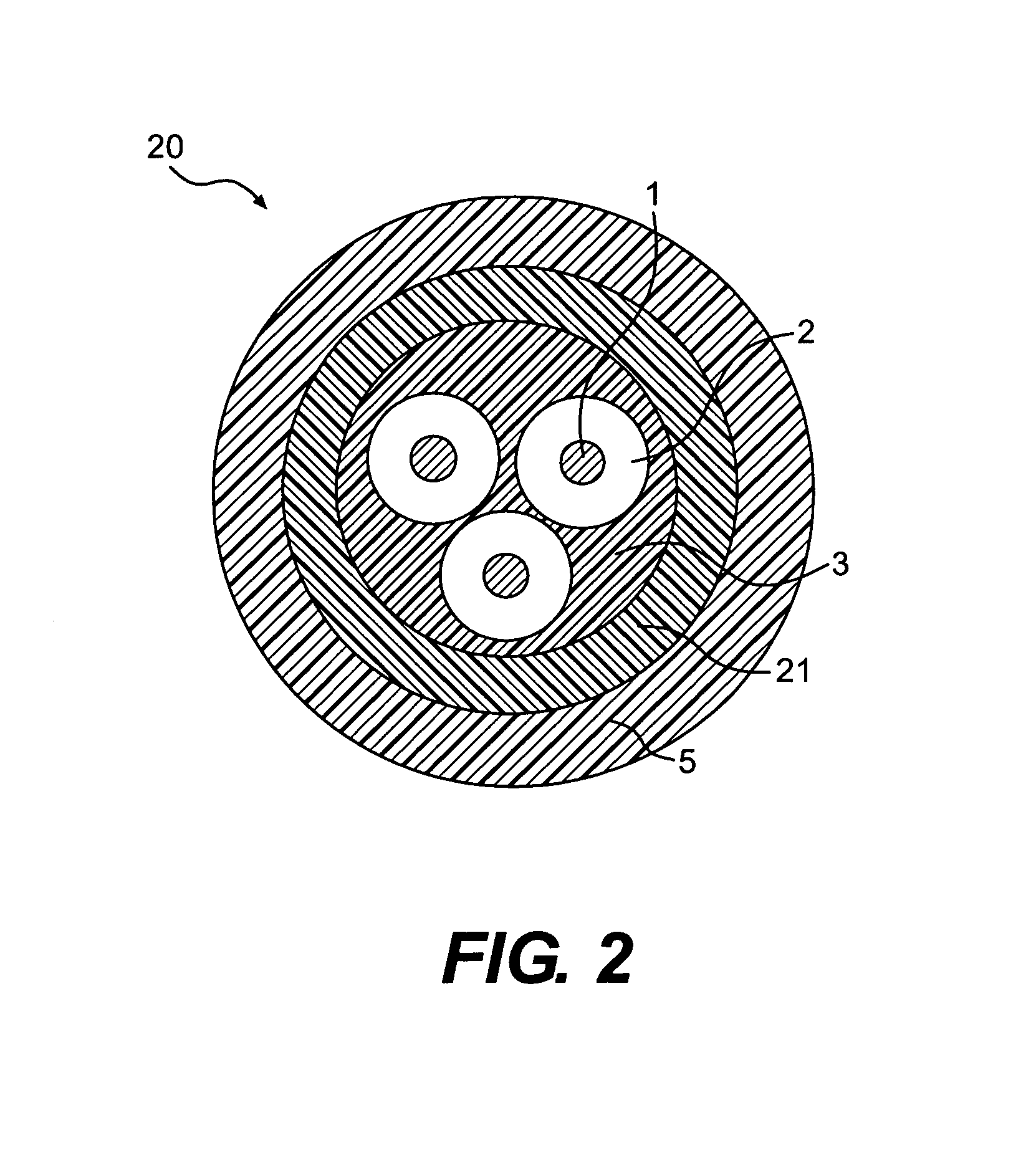
[0108]A low-voltage cable was prepared according to a construction scheme similar to that given in FIG. 2, the only difference being that the cable prepared was of bipolar type (rather than of tripolar type like the one illustrated in said FIG. 2).
[0109]Each of the two cores possessed by said cable consisted of a copper conductor (of cross section equal to 2.5 mm2) coated on the extrusion line with a 0.7 mm thick insulating layer based on silane-crosslinked polyethylene.
[0110]A layer of filling having a flame-retardant composition of known type was deposited, by extrusion, on said cores (each having an outside diameter of about 3.3 mm). More specifically, a flame-retardant composition comprising Engage 8452® (ethylene / octene copolymer from metallocene catalysis), Hydrofy G5® (ground natural magnesium hydroxide) and zinc stearate was used in this example. The thickness of said filling layer was equal to about 0.6 mm in the portion radially external to said cores, i.e. on the extrados...
example 4
[0130]A low-voltage cable of quadripolar type was prepared by means of a production process similar to that described in Example 2.
[0131]Each of the four cores possessed by said cable consisted of a copper conductor (of cross section equal to 120 mm2) coated on an extrusion line with a 1.2 mm thick insulating layer based on silane-crosslinked polyethylene.
[0132]A filling layer with a flame-retardant composition similar to that of Example 2 and a thickness equal to 1.4 mm was deposited, by extrusion, onto said cores.
[0133]In a successive stage, a flame-retardant coating having the composition given in Table 1 and a thickness equal to 2 mm was deposited on the filling layer thus obtained. In a similar manner to that described in Example 2, the expansion of the flame-retardant coating was obtained by adding into a hopper 2% by weight (relative to the total weight) of the expanding agent Hydrocerol® CF70 and producing an expansion degree equal to about 60%.
[0134]In a subsequent extrusio...
PUM
| Property | Measurement | Unit |
|---|---|---|
| Length | aaaaa | aaaaa |
| Length | aaaaa | aaaaa |
| Fraction | aaaaa | aaaaa |
Abstract
Description
Claims
Application Information
 - R&D
- Intellectual Property
- Life Sciences
- Materials
- Tech Scout
- Unparalleled Data Quality
- Higher Quality Content
- 60% Fewer Hallucinations
Browse by: Latest US Patents, China's latest patents, Technical Efficacy Thesaurus, Application Domain, Technology Topic, Popular Technical Reports.
© 2025 PatSnap. All rights reserved.Legal|Privacy policy|Modern Slavery Act Transparency Statement|Sitemap|About US| Contact US: help@patsnap.com