Check patentability & draft patents in minutes with Patsnap Eureka AI!

Apparatus and method for synchronizing clock modulation with power supply modulation in a spread spectrum clock system

Inactive Publication Date: 2006-05-23
IBM CORP
View PDF16 Cites 4 Cited by
  • Summary
  • Abstract
  • Description
  • Claims
  • Application Information

AI Technical Summary

Benefits of technology

[0007]It is an object of the invention to provide an apparatus and method for providing a spread spectrum clock signal in a manner which facilitates increased circuit performance.
[0008]This object is accomplished by modulating the supply voltage for a circuit in concert or synchronization with the circuit clock frequency. According to the present invention, the supply voltage for a circuit is increased as clock frequency is increased. However, in the portion of the clock frequency modulation cycle in which the clock frequency is decreasing, the supply voltage for the circuit is also decreased. This modulation of the circuit supply voltage level in concert with the system clock frequency provides the reduced EMI emission levels desired in spread spectrum clock arrangements, and simultaneously allows the circuit to function periodically at higher clock frequencies to improve overall system performance.

Problems solved by technology

However, as clock frequencies increase, complete EMI shielding becomes more difficult, and EMI emission levels may increase.
Thus, it is sometimes possible to meet regulatory limits for EMI emissions from a particular circuit by modulating the clock frequency in the circuit within a certain range about a centerline or nominal clock frequency.
All processors and other electronic devices that operate under control of a clock signal are limited in the clock frequency they can support, and thus the speed at which they can process data.
This operational speed limit is the result of certain critical paths between functional blocks which are clocked by a common clock signal.
This minimum instantaneous cycle time translates to a maximum clock frequency for the circuit and can never be violated without running the risk that the circuit will produce incorrect results for a given input.
However, increasing the supply voltage in a circuit will increase power dissipation in the circuit, and the thermal effect of this increased power dissipation may have a detrimental impact on the functionality and reliability of the circuit.
Thus, in many systems, increasing supply voltage level is not a viable choice to meet limitations on the maximum instantaneous frequency in a spread spectrum clock system.

Method used


Image

  • Apparatus and method for synchronizing clock modulation with power supply modulation in a spread spectrum clock system
  • Apparatus and method for synchronizing clock modulation with power supply modulation in a spread spectrum clock system
  • Apparatus and method for synchronizing clock modulation with power supply modulation in a spread spectrum clock system

Examples


Embodiment Construction

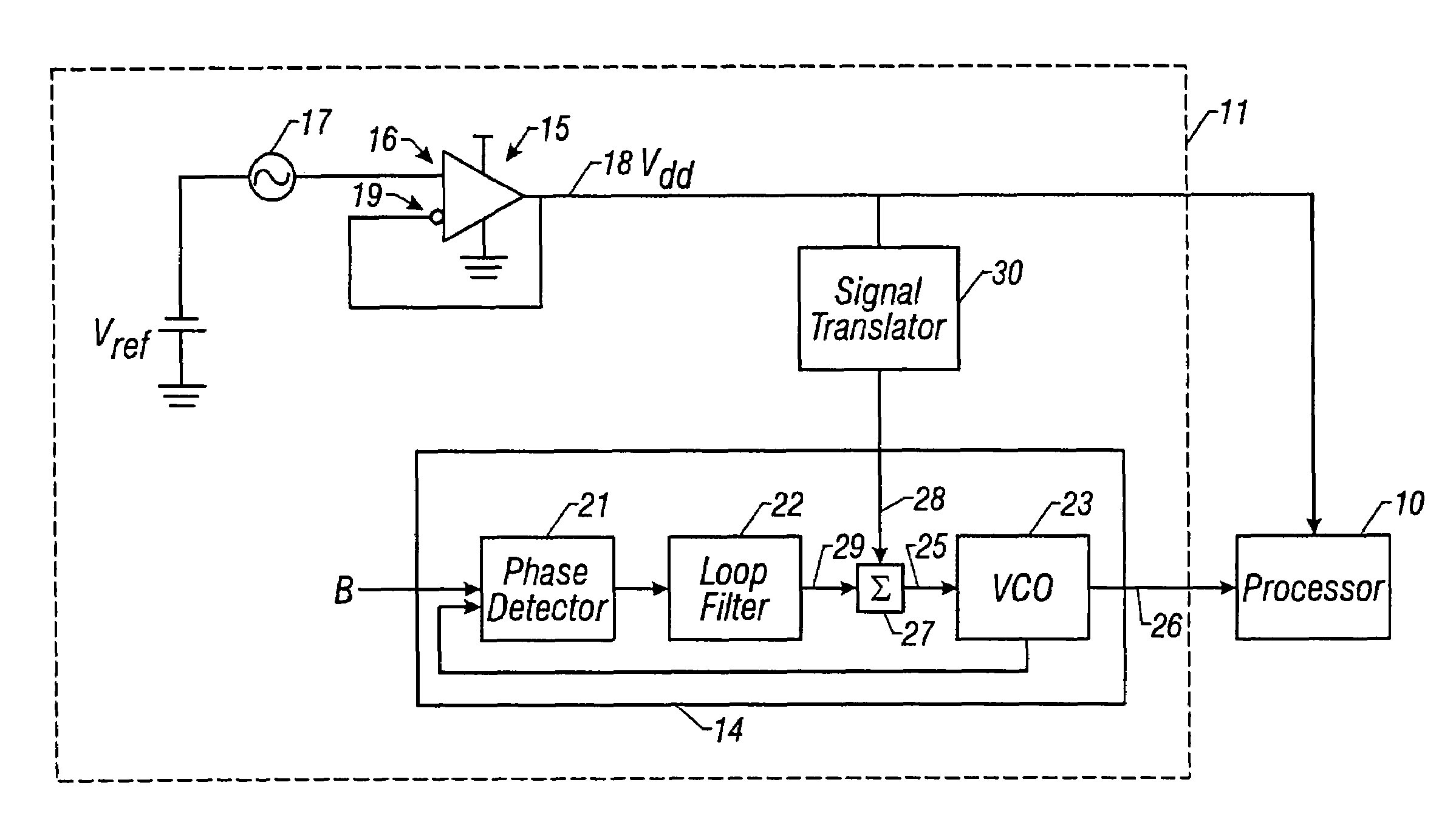
[0015]FIG. 1 illustrates electronic circuit 10 utilizing a spread spectrum clock system 11 embodying the principles of the invention. Circuit 10 is shown in the figure as a processor, but may comprise any circuit utilizing a DC supply voltage signal and a spread spectrum clock signal. Although, circuit 10 may be implemented as a separate integrated circuit chip which receives a DC supply voltage signal and the system clock from off-chip sources, the circuit may alternatively be implemented together with the spread spectrum clock system on a single integrated circuit chip. Also, circuit 10 and spread spectrum clock system 11 may be implemented using discrete electronic components within the scope of the following claims.

[0016]Spread spectrum clock system 11 includes a spread spectrum clock source 14 and a power supply 15. Clock source 14 provides the clock signal for circuit 10, while power supply 15 provides the supply voltage signal Vdd for the circuit. As used in this disclosure a...


PUM


Abstract

A spread spectrum clock system (11) modulates the supply voltage for a circuit (10) in concert with the circuit clock frequency (C). The system increases the supply voltage for the circuit (10) in phase with increases in the circuit clock frequency (C). However, in the portion of the clock frequency modulation period in which the clock frequency (C) is decreasing, the system (11) also decreases the supply voltage for the circuit (10). This relationship between the circuit supply voltage and circuit clock frequency (C) may be accomplished by modulating the output (18) of a power supply (15) for the circuit (10) and applying that modulated supply voltage signal through a signal translator (30) to control modulation of a clock source (14).

Description

TECHNICAL FIELD OF THE INVENTION[0001]The invention relates to electronic circuits that use high frequency clock signals. More particularly, the invention relates to an apparatus and method for modulating the supply voltage to a circuit along with the clock frequency in a spread spectrum clock arrangement.BACKGROUND OF THE INVENTION[0002]The high frequency clock signals used in many electronic circuits generate coincidental electromagnetic fields. These coincidental electromagnetic fields or emissions are known as electromagnetic interference or “EMI. ”The energy of EMI emissions from a particular circuit is directly proportional to the frequency of the clock signal used in the circuit.[0003]EMI emissions from electronic devices are regulated by governmental or other agencies to certain maximum allowable limits. Electronic equipment manufacturers must reduce EMI emissions as much as possible in order to maintain these emissions within the allowable limits. For example, electronic ci...

Claims


Application Information

Patent Timeline
IPC IPC(8): H03C3/09H03L7/06G06F1/04G06F1/08H03F3/38H03K3/00H03K3/02H03K5/13H03L7/16
CPCH03L7/06G06F1/08
Inventor WEEKLY, ROGER DONELL
Owner IBM CORP
Features
  • R&D
  • Intellectual Property
  • Life Sciences
  • Materials
  • Tech Scout
  • Unparalleled Data Quality
  • Higher Quality Content
  • 60% Fewer Hallucinations
Learn More