Process for the simultaneous removal of sulfur and mercury

a technology of simultaneous removal and sulfur, applied in the direction of separation processes, sulfur preparation/purification, hydrogen sulfides, etc., to achieve the effect of reducing the size of the unit, simplifying the process, and reducing the capital and operating costs of the plan

Inactive Publication Date: 2006-06-13
TDA RES
View PDF76 Cites 85 Cited by
  • Summary
  • Abstract
  • Description
  • Claims
  • Application Information

AI Technical Summary

Benefits of technology

[0027]The catalytic H2S oxidation technology of this invention can, in addition to removing mercury contaminant, provide a source of SO2, for sulfur recovery processes (Claus processes) eliminating the need for either shipping in liquid or compressed SO2 from an external source, or installing a sulfur burner system upstream of a liquid-phase or conventional Claus sulfur recovery plant. This lowers capital and operating costs of the plant by simp

Problems solved by technology

Such gas streams typically contain undesired levels of hydrogen sulfide or o

Method used


Image

  • Process for the simultaneous removal of sulfur and mercury
  • Process for the simultaneous removal of sulfur and mercury
  • Process for the simultaneous removal of sulfur and mercury

Examples


example 1

Equilibrium Calculations

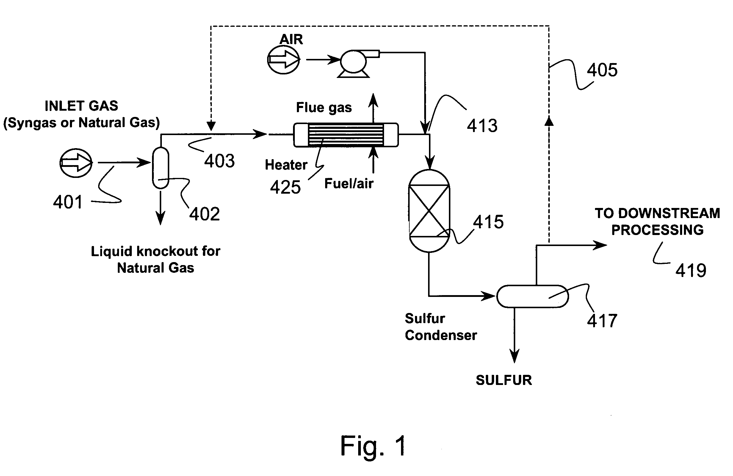
[0127]A typical composition of syngas is shown in Table 3. For high sulfur coal, the H2S concentration was assumed to be 10,000 ppm. For low sulfur coal, the H2S concentration was assume to be 100 ppm This composition was assumed for all the equilibrium and economic analyses in this section. The pressure was assumed to be 30 atmospheres. The syngas enters the direct oxidation and mercury removal reactor. The hydrogen sulfide is oxidized to sulfur and water (>90% conversion of H2S to S). The molar composition of the gas stream at the direct oxidation reactor outlet is shown in Table 4. The sulfur that is formed in the reactor is then cooled to between 120–140° C. in a sulfur condenser, where the sulfur vapors are condensed into molten sulfur. The molten sulfur drains out of the sulfur condenser and is collected for disposal.

[0128]FIG. 8 and FIG. 9 show the mercury removal efficiency and the resultant mercury concentration at the sulfur condenser outlet for bot...

example 2

Economics

[0130]An economic analysis of the Hg removal in the gasified stream has been undertaken. For high sulfur coal, 10,000 ppm H2S was used as the basis concentration in the gas. For low sulfur coal, 800 ppm was used H2S in the gas. For the high sulfur coal, assuming that all the sulfur is land filled (at an expense of $25 / ton) and adding an opportunity cost of $35 / ton (for not being able to use the sulfur), we arrive at a cost of $4795 / lb of mercury disposed. For the low sulfur coal, with the same assumptions, we arrive at a cost of $384 / lb of mercury.

[0131]In the second case, we assumed that, instead of land filling the sulfur, we will be distilling the sulfur so that, the mercury and sulfur are separated. Using this method, we have assumed that 90% of the sulfur will be free of Hg and will be available for sale. The remaining 10% of the sulfur which will be combined with the mercury will need to be land filled. In addition, we have calculated a capital cost of $20 / ton sulfur ...

example 3

Sulfur Dew Point

[0132]To avoid bed fouling or equipment plugging, it is preferred to operate a catalytic reactor of this invention in a pressure and temperature regime where any elemental sulfur formed in the reaction will remain in the vapor phase. The experiments reported show that for the best catalysts, the preferred operating temperature was 250° C. The dew point pressure for elemental sulfur at 250° C. determines the maximum concentration of sulfur vapor that can be present over the catalyst. This is linked to the maximum allowable H2S concentration via the selectivities to SO2 and sulfur. Higher selectivities to SO2 permit the processing gases with higher H2S concentrations.

[0133]An example of how the maximum allowable H2S concentration is calculated is discussed below. Sulfur vapor-liquid-equilibrium (VLE) calculations can be readily performed for different temperatures and concentrations of sulfur vapor. At T=250° C. for 2000 ppm of elemental sulfur vapor condensation start...


PUM

PropertyMeasurementUnit
Temperatureaaaaaaaaaa

Abstract

A process for removing hydrogen sulfide, other sulfur-containing compounds and/or sulfur and mercury from a gas stream contaminated with mercury, hydrogen sulfide or both. The method comprises the step of selective oxidation of hydrogen sulfide (H2S) in a gas stream containing one or more oxidizable components other than H2S to generate elemental sulfur (S) or a mixture of sulfur and sulfur dioxide (SO2). The sulfur generated in the gas stream reacts with mercury in the gas stream to generate mercuric sulfide and sulfur and mercuric sulfide are removed from the gas stream by co-condensation.

Description

CROSS-REFERENCE TO RELATED APPLICATIONS[0001]This application, which claims the benefit of U.S. Provisional Application 60 / 427,742, filed Nov. 19, 2002, is a continuation-in-part of pending U.S. application Ser. No. 10 / 358,404, filed Feb. 3, 2003 which in turn claims the benefit of U.S. Provisional Application 60 / 367,891, filed Mar. 25, 2002; U.S. Provisional Application 60 / 388,322, filed Jun. 13, 2002; and U.S. Provisional Application 60 / 420,694, filed October 22, 2002. Each of these applications is incorporated by reference herein in its entirety.BACKGROUND OF THE INVENTION[0002]The implementation of stricter emission limits for hydrogen sulfide (H2S) and sulfur dioxide (SO2) has stimulated the development and improvement of processes for the desulfurization of natural gas, synthesis gas, gasification streams and other gas streams used or generated in petroleum processing, oil recovery and coal utilization. For example, the level of H2S in natural gas must be lowered to 4 ppmv to ...

Claims


Application Information

Patent Timeline
IPC IPC(8): B01D53/64B01D53/48B01D53/52C01B17/04C01G13/00
CPCB01D53/64B01D53/8612C01B17/0447C01B17/0404C01B17/0434B01D2257/602
Inventor SRINIVAS, GIRISHCOPELAND, ROBERT J.
Owner TDA RES
Why Eureka
Try Eureka