Fluorescence observing apparatus

a fluorescence observing and apparatus technology, applied in the direction of radiation measurement, optical radiation measurement, spectral modifiers, etc., can solve the problems of low rate at which external light and background light (such as indoor illumination) are formed as noise components, extremely large apparatus size and extremely high cost, and weak light intensity of semiconductor lasers, etc., to achieve reduced oscillation threshold current, higher output or peak power, and suppressed rise in temperature of end face

Inactive Publication Date: 2006-06-13
FUJIFILM CORP +1
View PDF16 Cites 47 Cited by
  • Summary
  • Abstract
  • Description
  • Claims
  • Application Information

AI Technical Summary

Benefits of technology

[0026]If the aforementioned semiconductor laser is controlled to a predetermined temperature and below, the oscillating threshold current can be reduced and the dislocation propagation due to a rise in temperature of the end face can be suppressed. As a result, as the maximum output is not limited at thermal saturation, higher output or peak power can be obtained and the lifetime can also be considerably prolonged.
[0027]If a broad area type or surface emission type semiconductor laser is employed in place of the aforementioned semiconductor laser, a high-output excitation light source can be obtained more inexpensively.
[0028]If an array type semiconductor laser is used instead of the aforementioned semiconductor laser, excitation light having an output value obtained by integrating the light outputs of laser light emitted from a plurality of places can be emitted and therefore an excitation light source with high output is obtainable more cheaply.
[0029]If the aforementioned fluorescence observing apparatus further includes the aforementioned visible light irradiation means and normal image forming means, and if pulsed excitation light is irradiated during non-irradiation period of visible light, the respective light beams can be irradiated to a sample (e.g., an organism, etc.) so that they do not interfere with each other. As a result, a fluorescence image and a normal image can be formed more accurately.
[0030]If the aforementioned irradiation of excitation light is performed during the time that the normal image forming means is in a vertical blanking period, excitation light can be irradiated to the tissue of an organism without disturbing formation of a normal image.
[0031]If the aforementioned pulsed excitation light is formed from a plurality of pulses, for example, in the case where the aforementioned pulsed excitation light is formed from a single pulse obtained by pulse drive performed by a Q-switch, etc., an output equivalent to this single pulse can be obtained as the sum of a plurality of pulse outputs and therefore the pulse peak value can be reduced. As a result, the lifetime of the semiconductor laser can be prolonged and load on a laser driver circuit is reduced, whereby a further reduction in cost and size becomes possible.

Problems solved by technology

Furthermore, because the formation of a fluorescence image is performed within the blanking period after the formation of a normal image which is a short time, the rate at which external light and background light (such as indoor illumination) are formed as noise components, along with the fluorescence image is extremely low.
As described above, while excimer dye lasers and mercury vapor lamps have many advantages as an excitation light source, the apparatus is extremely large in scale and extremely high in cost.
The semiconductor laser, however, is weak in light intensity when employed as an excitation light source that is desired to emit light which has a wavelength belonging to a short wavelength region from ultraviolet rays to visible light.
In addition, if the semiconductor laser is oscillated to generate a peak value greater than or equal to the continuous maximum rated output value, a phenomenon called catastrophic optical damage (COD) will arise and the end face of the active layer of the semiconductor laser will be destroyed.
If the bandgap becomes narrower, the end face further absorbs light and generates heat, resulting in a rise in the temperature of the end face.
As a result, thermal run-away occurs and finally melts the end face.
Particularly, in the semiconductor laser with a large energy gap, which is employed in an excitation light source to emit light which has a wavelength belonging to a near ultraviolet region, it is difficult to inject a large current to enhance light output and also difficult to stably emit pulsed light having a peak value greater than or equal to the continuous maximum rated output value.

Method used


Image

  • Fluorescence observing apparatus
  • Fluorescence observing apparatus
  • Fluorescence observing apparatus

Examples


first embodiment

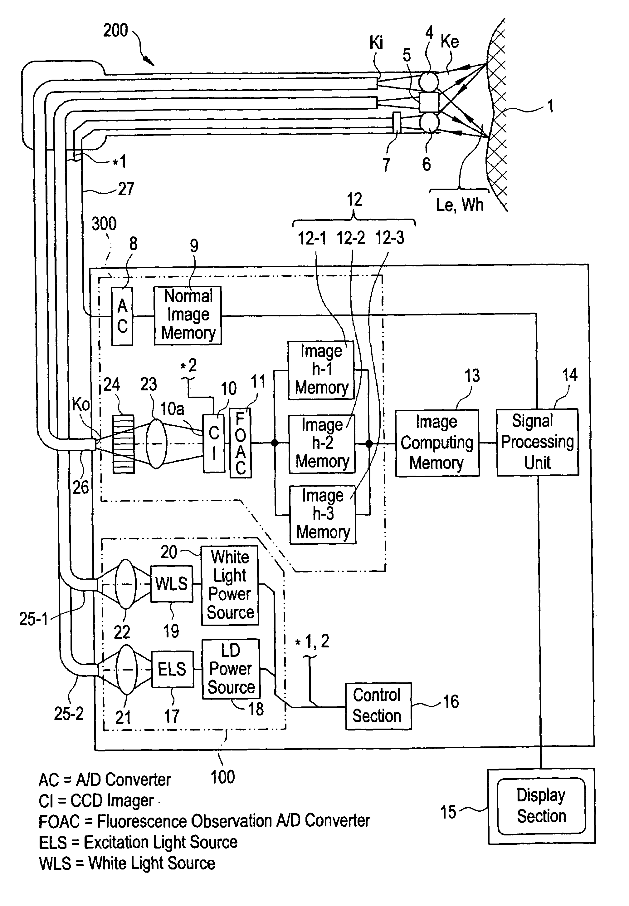
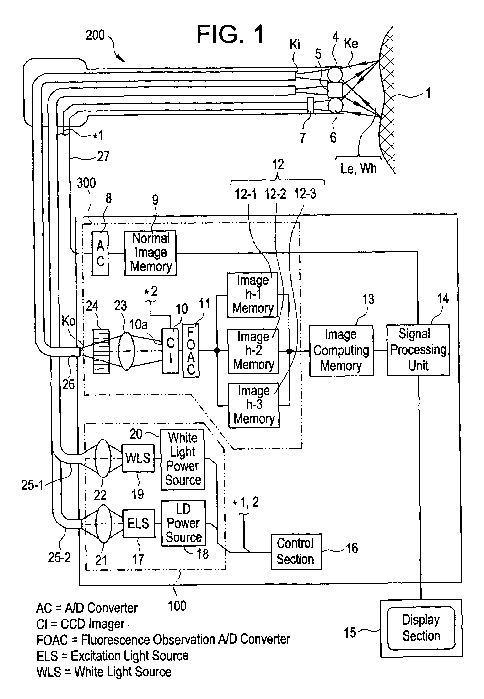
[0067]Referring now in greater detail to the drawings and initially to FIG. 1, there is shown a fluorescence observing apparatus constructed according to the present invention. The fluorescence observing apparatus comprises (1) a light source section 100 equipped with an excitation light source and a visible light (white light) source; (2) a flexible endoscope 200 for forming a normal image obtained by irradiating white light Wh guided from the light source section 100, to the tissue of an organism and also propagating the image of fluorescence (obtained by irradiating excitation light Le likewise guided from the light source section 100, to the tissue) to an optical fiber; (3) an image taking-in section 300 for taking in and storing the normal image and fluorescence image obtained by the endoscope 200, as image signals; (4) an image computing memory 13 equipped with the computation function of discriminating a cancerous tissue and a normal tissue by receiving and computing the imag...

second embodiment

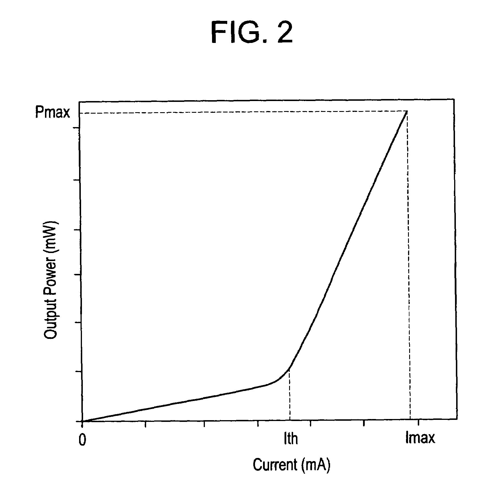
[0093]In the second embodiment, an excitation light source 17 employs an InGaN semiconductor later of multi-quantum cell structure (active layer InGaN / InGaN) of oscillating wavelength 400 nm and is pulse-operated with a dc bias current greater than or equal to an oscillating threshold current Ith (mA).

[0094]In addition, the pulse oscillation of the above-mentioned semiconductor laser is driven so that, as shown in FIG. 12, the integrated value Bo of the output values per unit time (per 1 / 60 sec) of LED light (spontaneous emission light), which occurs by dc bias current, and the integrated value Eo of the pulse oscillation output values per unit time become less than or equal to the integrated value Jo of the continuous maximum output values per unit time, and the pulse oscillation duty ratio is set so that a peak value greater than or equal to the continuous maximum output value is obtained. That is, the pulse oscillation duty ratio is set so that

Eo+Bo≦Jo.

[0095]Furthermore, since th...

third embodiment

[0103]Next, a description will be given of the operation in the above-mentioned

[0104]The fluorescence observing apparatus of the third embodiment is controlled by a controller 16 in accordance with a timing chart shown in FIG. 18. As shown in the timing chart of FIG. 18, pulsed excitation light Le, formed from 3 divided pulses having the same rectangular waveform, is emitted from an excitation light source 17. The excitation light Le is guided to an endoscope 200 through an excitation light condenser lens 21 and an excitation light guide 25-2 and is irradiated toward a tissue 1 through an illuminating lens 5.

[0105]The fluorescence, emitted from the tissue 1 by irradiation of the excitation light Le, is formed on an end face Ki of a fluorescence image fiber 26 by an fluorescence image objective lens 4 and is propagated to the other end face Ko. With respect to the fluorescence image propagated to the end face Ko, the excitation light Le contained in the fluorescence Ke (which is a me...


PUM

PropertyMeasurementUnit
emission timeaaaaaaaaaa
melting pointaaaaaaaaaa
pulse widthaaaaaaaaaa

Abstract

A fluorescence observing apparatus including a light source for emitting excitation light, an excitation light irradiation section for irradiating the excitation light to a sample, and a fluorescence measurement section for measuring fluorescence emitted from the sample by the irradiation of the excitation light. In the fluorescence observing apparatus, a GaN semiconductor laser is employed as the light source.

Description

BACKGROUND OF THE INVENTION[0001]1. Field of the Invention[0002]The present invention relates to a fluorescence observing apparatus for measuring fluorescence emitted from a sample (e.g., an organism, etc.) by irradiation of excitation light to provide information which is used for diagnosis, etc., and more particularly to a fluorescence observing apparatus that employs a semiconductor laser as its excitation light source.[0003]2. Description of the Related Art[0004]A diagnosis instrument, etc., for acquiring the intensity and spectrum of fluorescence emitted from a sample (e.g., an organism, etc.) by irradiation of excitation light to obtain information which is used for diagnosis, are known. These diagnosis instruments employ a method of detecting fluorescence emitted when excitation light for diagnosis is irradiated to the tissue of an organism, a method of detecting fluorescence emitted by irradiating excitation light to the tissue of an organism which has beforehand absorbed a ...

Claims


Application Information

Patent Timeline
Patent Type & Authority Patents(United States)
IPC IPC(8): A61B6/00A61B1/00G02B23/24A61B1/04A61B1/06A61B5/00G01N21/64G02B21/00G02B23/26H01S5/024H01S5/18H01S5/323H01S5/343H01S5/40H04N7/18
CPCA61B5/0071A61B5/0084G01N21/6456G01N21/645G01N2201/0612G01N2021/6421
Inventor SENDAI, TOMONARIHAYASHI, KATSUMIHAKAMATA, KAZUOHAYAKAWA, TOSHIROOKAZAKI, YOJIMATSUMOTO, KENJI
Owner FUJIFILM CORP
Why Eureka
Try Eureka