Method for hydrogenating carbon dioxide, treating apparatus, and basic material for hydrogenation

a carbon dioxide and hydrogenation technology, applied in the field of hydrogenation process, can solve the problems of low efficiency of these techniques, low rate of processing, and serious drawbacks of conventional techniques, and achieve the effects of high temperature, low conversion rate, and high capacity for processing carbon dioxid

Inactive Publication Date: 2006-06-20
MATSUI
View PDF6 Cites 3 Cited by
  • Summary
  • Abstract
  • Description
  • Claims
  • Application Information

AI Technical Summary

Benefits of technology

[0007]The present invention considerably differs from conventional processing techniques as mentioned above in ideas. An object of the present invention is to provide a process for hydrogenating carbon dioxide that is capable of processing a large quantity of carbon dioxide to generate a large quantity of methanol as a main product, thereby engaging with the rapidly spreading issue of global warming. It is another object of the present invention to yield significant economic effects through the use of the thus obtained methanol. Such methanol has potential to be an important fuel for the future, and can be used as an alternative to fossil fuels, an agricultural material for growing plants, and for other basic materials. Thereby, use of the aforementioned process can be developed as a social enterprise.
[0017]The present invention is intended to yield a large quantity of methanol as well as possess a high capacity for processing carbon dioxide. Mainly, water is rapidly and continuously discharged to the outside of the reaction system at the same time as the generation of the product shown in the right-hand side of Chemical Formula 1. The low conversion rate of approximately 40% due to thermodynamic restrictions is maximized to attain the above object. More specifically, when the porous body used in the present invention as shown in FIG. 1 migrates forward between groups 12 and 13 of drive rollers which have elastic surfaces so as to move in conjunction with the adjacent rollers that are in close contact with each other as shown in FIG. 5, the inner spaces 14 and 15 (FIG. 5) formed within the groups of rollers become sealed, have a high temperature, and have a high pressure because of the containment of carbon dioxide and hydrogen gas. Thus, methanol and water vapor are generated by the reaction represented by Chemical Formula 1. In such a state, cold air or coolants 23a and 23b are supplied from the outer spaces 22a and 22b, which are located outside of the aforementioned inner spaces and have conditions of room temperature and normal pressure, toward the circumscribed surfaces 24a and 24b formed along the groups of rollers. Thus, the aforementioned surfaces 24a and 24b of the groups 12 and 13 of rollers, respectively, are located contiguously with the circumferences of the tangent planes with which the groups of rollers are in close contact. These spaces are cooled even though the thermal conductivity of rollers is low. Thus, as the water vapor in the inner spaces or the water vapor containing the generated methanol reaches the dew point, thin liquid layers 25a and 25b are formed on the tangent planes of the aforementioned rotating drive rollers, and the water-sealed state can be maintained. It should be noted that the surfaces of the above groups of rollers must have hydrophilic properties such as those of a titanium oxide coating in order to form the liquid layers. Also, it is advantageous to provide fine irregularities, streak patterns, and the like on the surfaces so as to impart water-retentive properties without interfering with the sealed state.

Problems solved by technology

Disadvantageously, the efficiency of these techniques is low, and the rate of processing is much lower than that of carbon dioxide emission.
There exits many literatures concerning the hydrogenation of carbon dioxide, although conventional techniques suffer from serious drawbacks as described below.
According to this chemical formula, the conversion rate at chemical equilibrium cannot be exceeded due to thermodynamic restrictions.
It is highly insufficient to conduct the above reaction using a main catalyst of zinc or copper oxide since the conversion rate is as low as approximately 40% under reaction conditions of approximately 200° C. to 250° C. at 50 atm to 100 atm, and many substances remain unreacted.
Thus, conventional techniques are not yet sufficient due to the necessity for considerably complicated equipment, as well as the existence of technical and practical difficulties.

Method used


Image

  • Method for hydrogenating carbon dioxide, treating apparatus, and basic material for hydrogenation
  • Method for hydrogenating carbon dioxide, treating apparatus, and basic material for hydrogenation
  • Method for hydrogenating carbon dioxide, treating apparatus, and basic material for hydrogenation

Examples


example 1

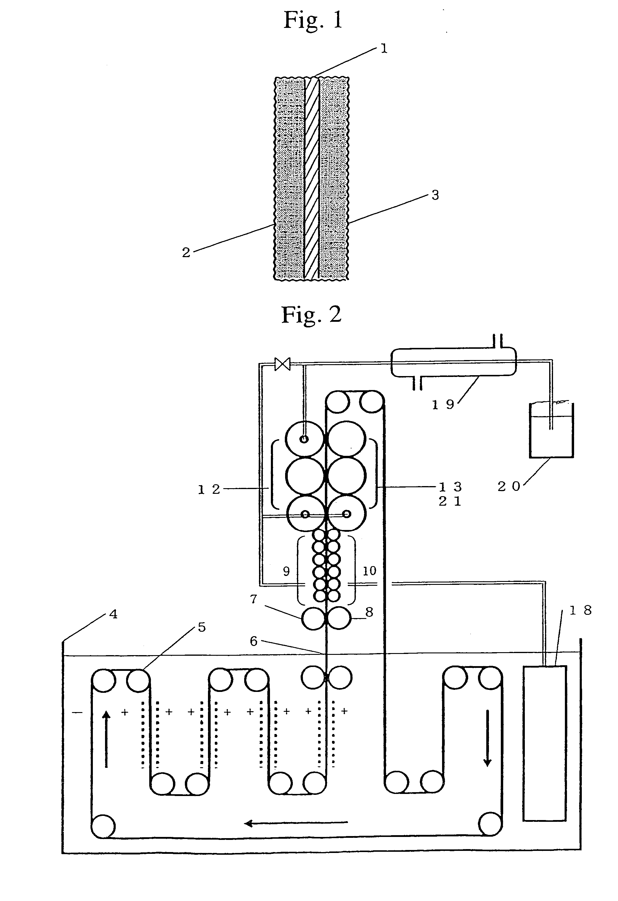
[0027]As shown in FIG. 2, a strip of thin copper base plate 1 (thickness: 0.1 mm) is electrolyzed while being guided in the upward and downward directions among plural drive rollers 5 in an electrolyte accommodated in an electrolytic bath 4, and it migrates forward. An electrolyte to be used is an emulsion comprising 50 g of zinc oxide powder per liter of a solution comprising 100 g of caustic potash per liter thereof. The base plate 1 that migrates within an electrolyte while employing anode of insoluble plates, such as zinc plates, immobilized on both of its sides. The base plate 1 continuously migrates forward while being electrolyzed cathodically at 5 A / dm2 by adopting the insoluble plates as anodes and the base plate 1 as a cathode. Active porous metallic zinc layers are deposited and immobilized on both sides of the base plate 1 during this electrolysis. The amount of zinc to be deposited is adjusted by regulating the current density of the electrolysis on both sides of the ba...

example 2

[0038]The description made in Example 1, line 10 on page 8 to line 3 on page 9, is also applicable in this example.

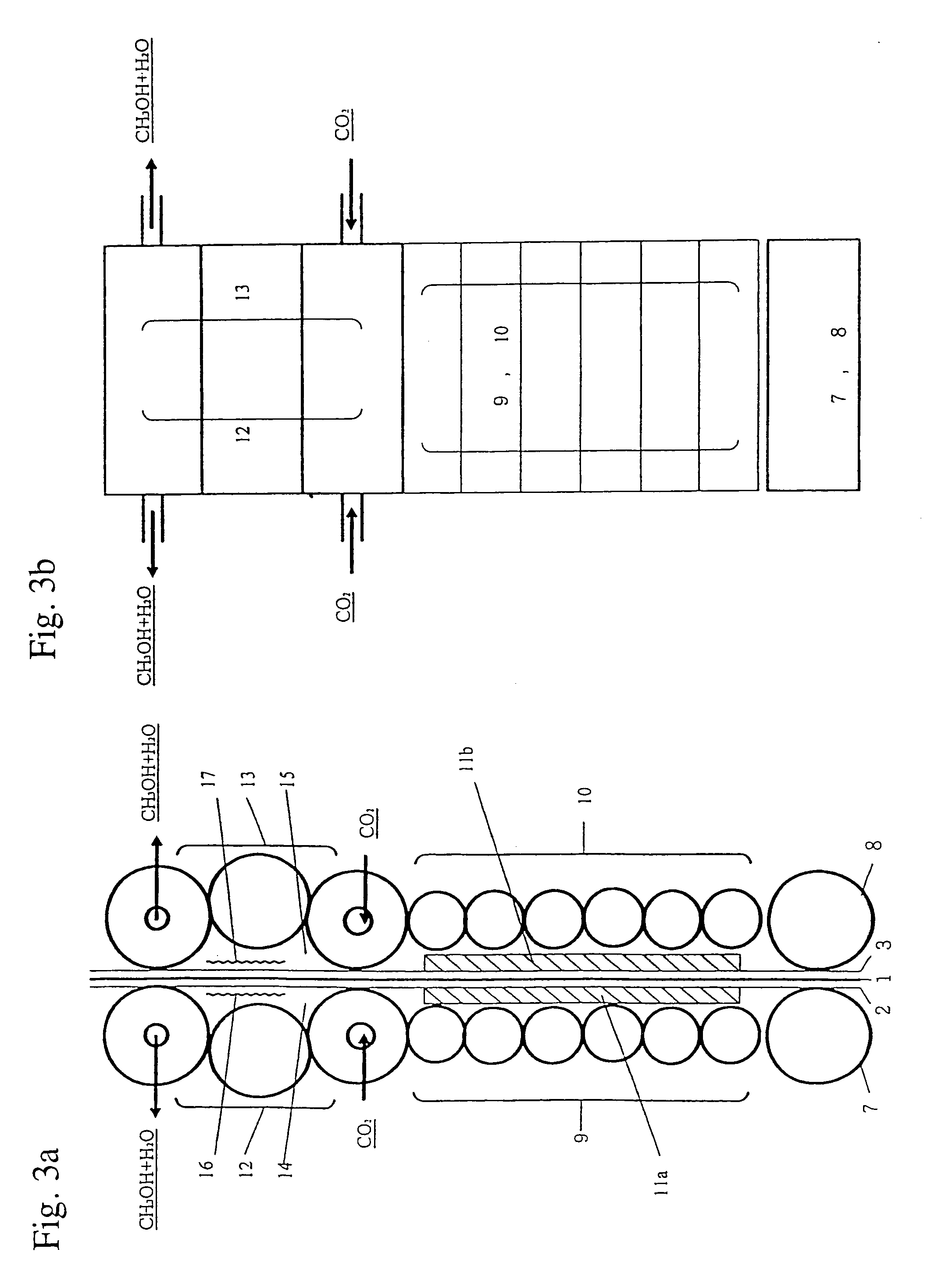
[0039]As shown in FIG. 2, when copper oxide powders are sprinkled on the porous metallic zinc layer 2 provided on one side of the base plate 1 before the base plate enters to roller 7, portions of the porous layer are reduced to metallic copper with the aid of metallic zinc. However, other portions form a porous metallic zinc layer comprising copper oxide. In such a case, the aforementioned additional substances that can be used as subcatalyst for zinc oxide or copper oxide catalysts may be incorporated therein.

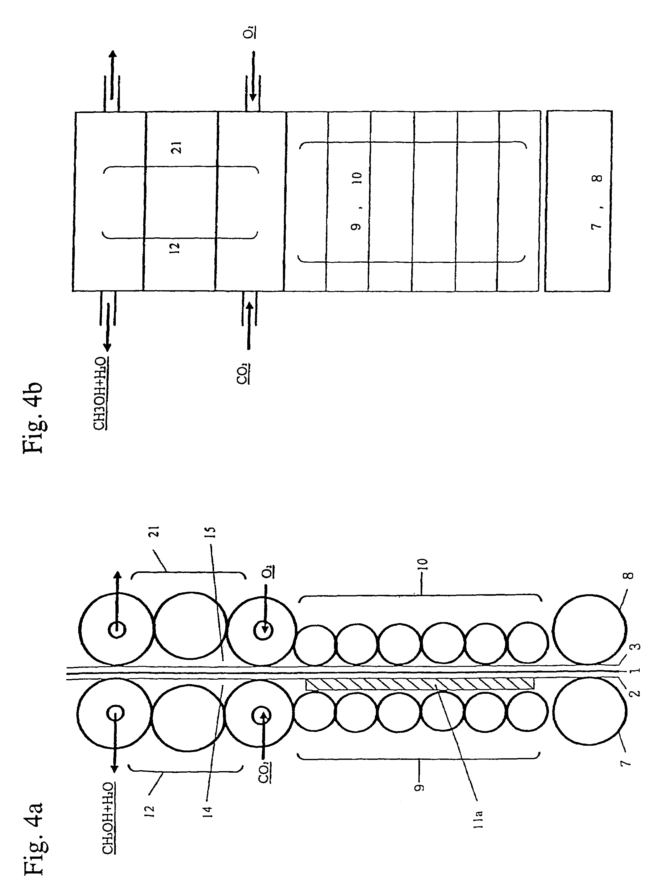
[0040]Thus, the base plate 1 migrates upward to be sandwiched between plural rotating drive rollers. FIG. 4a (an elevational view) and FIG. 4b (a plane view) are detailed and enlarged diagrams showing this procedure. The drawings are roughly divided to show the group 9 of drive rollers for generating hydrogen as shown in Chemical Formula 3, the group 10 of drive ...

example 3

[0045]The description made in Example 1, line 10 on page 8 to line 10 on page 9, is also applicable in this example.

[0046]In this example, the base plate 1 migrates upward between plural rotating drive rollers. FIGS. 5 is an enlarged diagram showing a major part of an apparatus for hydrogenating carbon dioxide, and show a process for hydrogenating carbon dioxide for additionally explaining the apparatus and the process described in Example 1 and shown in FIG. 3a and FIG. 3b. More specifically, with the utilization of the apparatus and the process for hydrogenating carbon dioxide, water can be immediately and continuously discharged to the outside of the reaction system simultaneously with the generation of the reaction product shown in the right-hand side of Chemical Formula 1, thereby enhancing the rate of conversion with low chemical equilibrium and enhancing the yield of methanol. The explanation thereof is the same as described from line 10 on page 6 to line 24 on page 7.

[0047]I...


PUM

PropertyMeasurementUnit
temperatureaaaaaaaaaa
partial pressureaaaaaaaaaa

Abstract

A process for hydrogenating carbon dioxide to generate methanol. In the process, a strip of copper base plate is transported by the groups of rotating drive rollers to deposit porous metallic zinc on the copper base plate. Hydrogen is generated from the porous metallic zinc upon electrochemical reactions in the inner space sealed with the above groups of rollers. Simultaneously, zinc oxide and copper oxide catalysts are formed on the porous metallic zinc. Carbon dioxide is introduced into the sealed inner space under high-temperature and high-pressure to generate methanol by hydrogenation.

Description

TECHNICAL FIELD[0001]The present invention relates to a process for hydrogenating carbon dioxide using a synthetic catalyst mainly composed of a mixed oxide of zinc and copper, thereby generating methanol as a main product, and an apparatus therefor.BACKGROUND ART[0002]At present, global warming is considered an urgent issue and one of the most important tasks for humanity to deal, with as it could endanger the existence of humans. Carbon dioxide, a large quantity of which has been accumulated in the world due to the use of fossil fuels, accounts for much of the global warming phenomenon. Further, the rate of carbon dioxide emission has recently increased exponentially, and numerous intensive studies have been conducted all over the world to develop techniques for dealing with this issue.[0003]Examples of conventional techniques for hydrogenating carbon dioxide in order to fix carbon dioxide include photoelectrochemical techniques utilizing natural energy, such as sunlight, and bioc...

Claims


Application Information

Patent Timeline
Patent Type & Authority Patents(United States)
IPC IPC(8): C07C27/00C25B3/00C07C29/152C07C29/153C07C29/154C07C45/00C25D9/08
CPCC07C29/152C07C29/153C07C29/154C07C45/00C12C11/02C25D9/08C07C31/04C07C47/04Y02E60/36Y02P20/582
Inventor MATSUI
Owner MATSUI
Why Eureka
Try Eureka