Integrated reformer and shift reactor

a technology of hydrocarbon fuel and reformer, which is applied in the direction of combustible gas production, physical/chemical process catalysts, lighting and heating apparatus, etc., can solve the problems of carbon monoxide being considered an undesirable reaction product, harming the catalyst used, and another challenge for the proposed integrated system with resp

Inactive Publication Date: 2006-06-27
NUVERA FUEL CELLS
View PDF468 Cites 93 Cited by
  • Summary
  • Abstract
  • Description
  • Claims
  • Application Information

AI Technical Summary

Benefits of technology

[0037]The first helical tube is preferably configured to permit the oxygen-containing gas to travel through each coiled section in a direction opposite to a direction traveled by the oxygen-containing gas through an adjacent coiled section. A first

Problems solved by technology

For example, carbon monoxide may be considered an undesirable reaction product on board a fuel cell powered automobile.
In short, the challenge for the smaller-scale, dynamic, integrated processors is the idea that what goes in the reformer, must come out at the same end as the desired hydrogen gas.
Another challenge exists for the proposed integrated systems with respect to the hydrocarbon feed stock.
These fuels were not designed as a feed stock for generating hydrogen.
Because of this, integrated systems are challenged to be able to handle the wide variety of hydrocarbons in the feed stock.
For example, certain reforming byproducts such as olefins, benzene, methyl amide, and higher molecular weight aromatics can cause harm to catalysts used in reforming or purifying steps and may harm the fuel cell itself.
Impurities in these fuels such as sulfur and chlorine can also be harmful to reactor catalysts and to the fuel cell.
This poses a problem for an integrated reactor system that is not faced by traditional reforming processes where significant carbon monoxide concentrations are either a useful co-product, or can be separated from the product gas without undue burden on the system economics as a whole.
Accordingly, techniques which separate carbon monoxide from hydrogen, such as pressure swing adsorption (“PSA”) or hydrogen permeable membrane separation, have the deficit of having to provide an alternate means for disposal or storage of the carbon monoxide.
Both of the aforementioned techniques also suffer in efficiency as neither converts the carbon monoxide (in the presence of water) to maximize hydrogen production.
PSA also suffers from high cost and space requirements, and presents a likely unacceptable parasitic power burden for portable power or transportation applications.
At the same time, hydrogen permeable membranes are expensive, sensitive to fouling from impurities in the reformate, and

Method used


Image

  • Integrated reformer and shift reactor
  • Integrated reformer and shift reactor
  • Integrated reformer and shift reactor

Examples


Embodiment Construction

[0068]While the present invention is susceptible of embodiment in many different forms, this disclosure will described in detail, preferred embodiments of the invention with the understanding that the present disclosure is to be considered as an exemplification of the principles of the invention and is not intended to limit the broad aspect of the invention to the embodiments discussed or illustrated.

I. System and Sub-System Structure

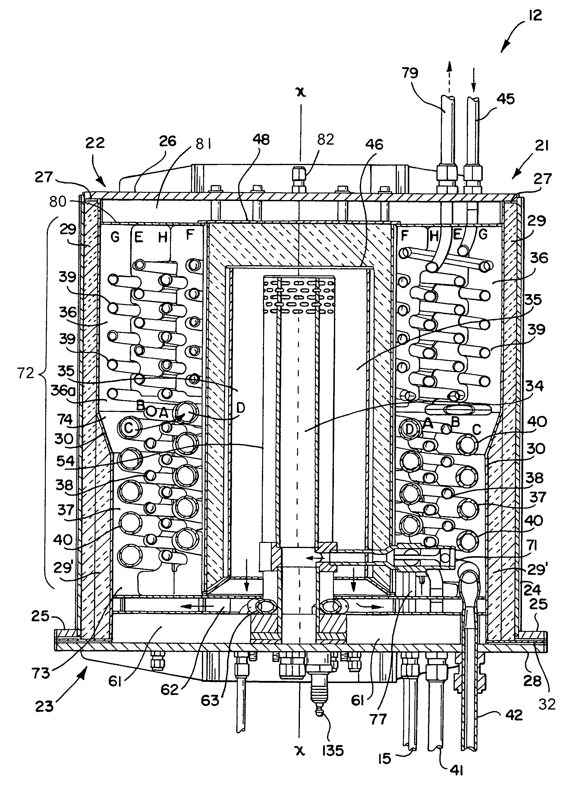
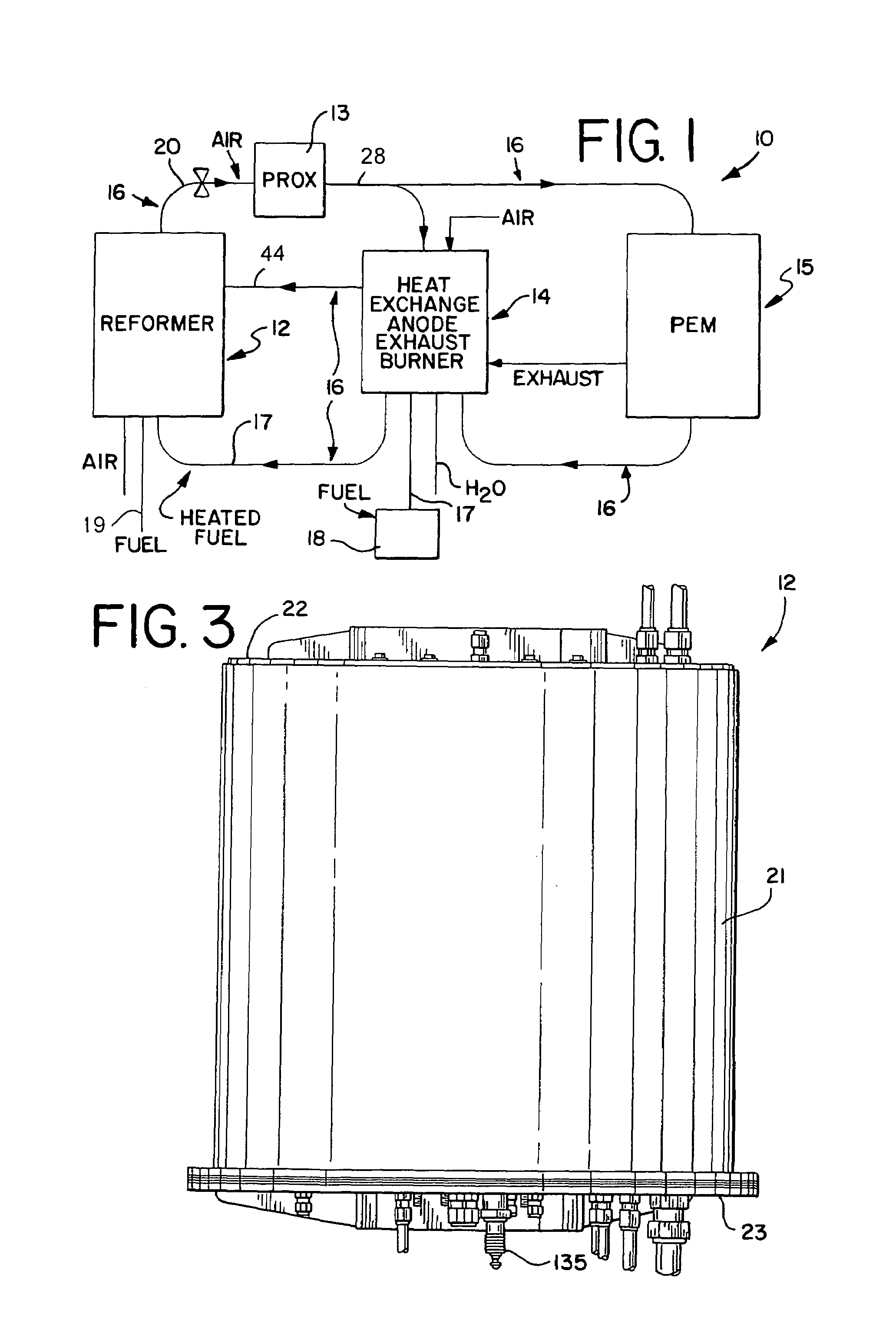
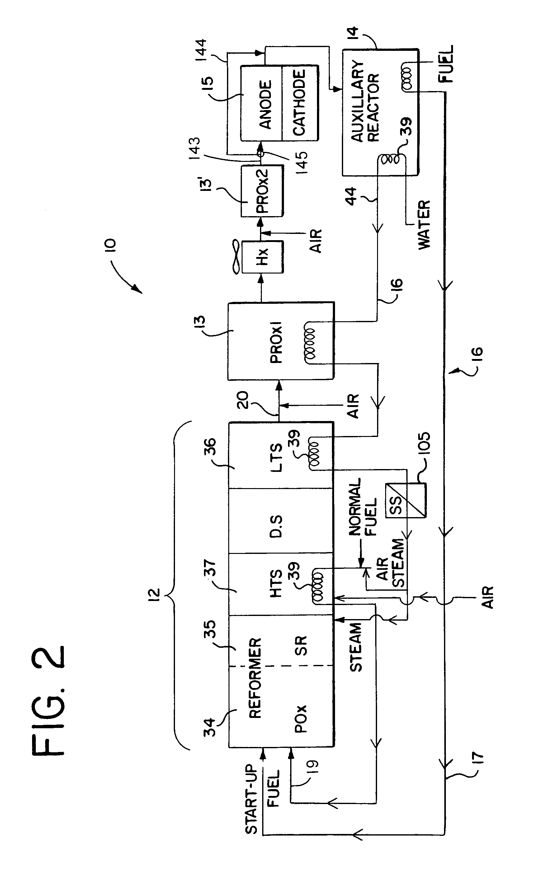
[0069]Referring generally to the appended FIGS. 1–28, the hydrocarbon reforming process and apparatus of the present invention can be more readily understood. The disclosed hydrocarbon reforming system architecture is generally referenced by the number “10” in the following disclosure and drawings. Other specific components, such as the reforming chambers, catalyst beds, auxiliary reactors (e.g., PrOx reactors, tail gas combusters, etc.), and their respective parts, are similarly and consistently numbered throughout this disclosure. While the present hy...


PUM

PropertyMeasurementUnit
Temperatureaaaaaaaaaa
Pressureaaaaaaaaaa
Flow rateaaaaaaaaaa

Abstract

A hydrocarbon fuel reformer for producing diatomic hydrogen gas is disclosed. The reformer includes a first reaction vessel, a shift reactor vessel annularly disposed about the first reaction vessel, including a first shift reactor zone, and a first helical tube disposed within the first shift reactor zone having an inlet end communicating with a water supply source. The water supply source is preferably adapted to supply liquid-phase water to the first helical tube at flow conditions sufficient to ensure discharge of liquid-phase and steam-phase water from an outlet end of the first helical tube. The reformer may further include a first catalyst bed disposed in the first shift reactor zone, having a low-temperature shift catalyst in contact with the first helical tube. The catalyst bed includes a plurality of coil sections disposed in coaxial relation to other coil sections and to the central longitudinal axis of the reformer, each coil section extending between the first and second ends, and each coil section being in direct fluid communication with at least one other coil section.

Description

RELATED REFERENCES[0001]The present invention claims priority of U.S. Provisional Patent Application Nos. 60 / 132,184 and 60 / 132,259, both filed on May 3, 1999. The present invention also claims priority of and is a continuation-in-part of U.S. patent application Ser. No. 09 / 006,727, filed on Jan. 14, 1998, which became U.S. Pat. No. 6,245,303 on Jun. 12, 2001. The present invention also claims priority of and is a continuation-in-part of U.S. patent application Ser. No. 08 / 703,398, filed on Aug. 26, 1996, which became U.S. Pat. No. 6,126,908 on Oct. 3, 2000.GOVERNMENT RIGHTS[0002]The United States Government has a paid-up license in this invention and the right in limited circumstances to require the patent owner to license others on reasonable terms as provided for by the terms of DE-FC02-97EE50472 awarded by the Department of Energy (DOE).TECHNICAL FIELD[0003]The present invention is generally related to an integrated hydrocarbon fuel reforming system for reforming a gaseous or li...

Claims


Application Information

Patent Timeline
IPC IPC(8): B01J8/02B01J8/04
CPCB01J8/0465B01J8/048B01J8/0488B01J8/0496B01J19/0046C01B3/382C01B3/48B01J8/0469C01B2203/82B01J2208/00203B01J2208/0053B01J2208/00849C01B2203/0244C01B2203/0288C01B2203/044C01B2203/045C01B2203/047C01B2203/0485C01B2203/066C01B2203/0894C01B2203/1058C01B2203/1229C01B2203/1235C01B2203/127C01B2203/1276C01B2203/146C01B2203/1604C01B2203/1614C01B2203/1685C01B2203/169
Inventor BENTLEY, JEFFREY M.CLAWSON, LAWRENCE G.MITCHELL, WILLIAM L.DORSON, MATTHEW H.
Owner NUVERA FUEL CELLS
Why Eureka
Try Eureka