Polar modulation transmitter

a polar modulation and transmitter technology, applied in the field of wireless communication, can solve the problems of limiting battery life, polar modulation, power efficiency loss, etc., and achieve the effect of improving performance in polar modulation transmitters and reducing the adjacent channel power ratio (acpr)

Active Publication Date: 2006-07-04
UNWIRED PLANET
View PDF11 Cites 103 Cited by
  • Summary
  • Abstract
  • Description
  • Claims
  • Application Information

AI Technical Summary

Benefits of technology

[0011]The present invention comprises a method and apparatus to improve performance in a polar modulation transmitter that generates an envelop-and-phase modulated radio frequency output signal responsive to separate envelope and phase modulation information signals. In one or more exemplary embodiments, the transmitter

Problems solved by technology

Biasing transmitter power amplifiers to linear operating points may satisfy amplifier linearity requirements, but does so at the expense of power efficiency.
Such power inefficiency runs at cross-purposes to achieving low overall operating power and, in the context of portable communication devices, severely limits battery life.
However, as with most technical innovations, polar modulation has certain disadvantages or, more properly stated, certain limitations, that present challenges to its use.
Such challenges involve the expansion of phase and amplitude bandwidths associated with “unwrapping” the phase and amplitude information.
As such, polar modulation requirements may not be easily met

Method used


Image

  • Polar modulation transmitter
  • Polar modulation transmitter
  • Polar modulation transmitter

Examples


Embodiment Construction

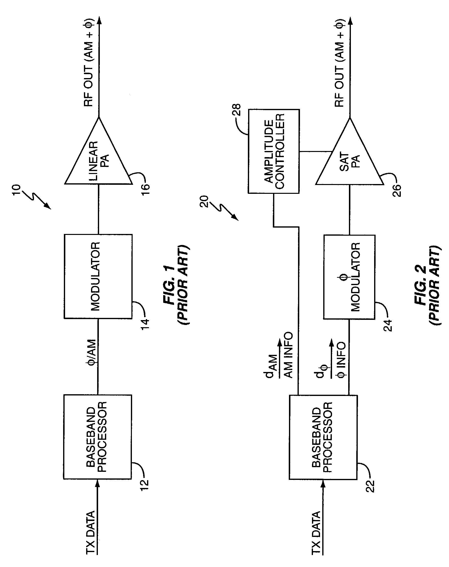
[0030]FIG. 1 illustrates a typical linear transmitter 10 for use in a wireless communication device or system. Transmitter 10 comprises, in this simplified depiction, a baseband processor 12, a modulator 14, and a linear power amplifier 16. Desired transmit data, such as a digital bit stream of channel-encoded transmit data is converted into a corresponding stream of modulation symbols including both phase and amplitude modulations by the baseband processor 12. These modulation symbols drive the modulator 14, which imparts corresponding phase and amplitude modulation to a RF carrier frequency signal (not shown). The modulated carrier signal output from modulator 14 serves as an input signal to the linear power amplifier 16, which generates a corresponding RF output signal having both phase and linear amplitude modulations and suitable for transmission via an associated antenna assembly (not shown).

[0031]Key to its acceptable performance, the linear power amplifier 16 must impart lin...


PUM


Abstract

A polar modulation transmitter circuit provides reduced ACPR in its output signal by controlling the relative delay between its envelope and phase modulation operations based on direct or indirect feedback measurement the output signal's ACPR. Such measurement and associated control may be based on a delay controller that includes an ACPR measurement circuit and a delay control circuit. Additionally, or alternatively, the polar modulation transmitter circuit provides a greatly extended transmit power control range by using a staged amplifier circuit that includes a driver amplifier circuit operating in combination with a power amplifier circuit to impart desired envelope modulation. In an exemplary embodiment, the driver amplifier circuit is implemented as differential transistor pairs responsive to tail current modulation. As such, the driver amplifier circuit is suited in particular for economical and space saving integration within a transmitter or transceiver integrated circuit (IC).

Description

BACKGROUND OF THE INVENTION[0001]The present invention generally relates to wireless communication and particularly relates to polar modulation methods and apparatus.[0002]Current and evolving wireless communication standards, such as WCDMA (Wideband CDMA), EDGE (Enhanced Data Rates through GSM Evolution), and GSM (Global System for Mobile communications), combine a variety of digital modulation formats. Such formats include 8-QPSK modulation, various QAM implementations, GMSK modulation, etc. Of the several aims embodied in these current and developing wireless standards are increased data rates and increased spectral efficiency.[0003]Achieving such aims involves, in part, the use of relatively complex digital modulation formats, which impose stringent linearity requirements for transmit signal generation. Biasing transmitter power amplifiers to linear operating points may satisfy amplifier linearity requirements, but does so at the expense of power efficiency. Such power inefficie...

Claims


Application Information

Patent Timeline
IPC IPC(8): H04B1/04H03F1/02H03F3/24H04L27/36
CPCH03F1/0211H03F3/24H04L27/368H04L27/361H03F2200/504H03F2200/331
Inventor HADJICHRISTOS, ARISTOTLE
Owner UNWIRED PLANET
Why Eureka
Try Eureka