Antenna structure for inductively coupled plasma generator

an inductively coupled plasma and generator technology, applied in nuclear reactors, greenhouse gas reduction, nuclear engineering, etc., can solve the problems of difficult control of the distribution of inductive electric fields, complex and difficult application of oxide etching process, loss of ions and electrons at the internal wall of the chamber, etc., to facilitate inductance matching, improve plasma uniformity, and effectively reduce an electrical field

Inactive Publication Date: 2006-07-18
PLASMART CO LTD
View PDF14 Cites 16 Cited by
  • Summary
  • Abstract
  • Description
  • Claims
  • Application Information

AI Technical Summary

Benefits of technology

[0015]To solve the above-described problems with prior art, the present invention provides a plasma generator with improved antenna structure, which can prevent dusty particles from being generated without applying a high voltage, which can uniformly apply a voltage throughout the antenna structure, and which allows a plasma density distribution to be uniform and symmetrical with respect to a rotating direction inside a chamber, thereby effectively plasma-processing a large-diameter wafer or large-area flat-panel display device.
[0017]In the present invention, since the respective antennas are electrically connected in parallel, the overall impedance of the antennas is reduced, thereby solving the problem of nonuniformity in voltage and attaining a uniform voltage distribution with a low voltage applied. Thus, a reduction in yield due to application of a high voltage can be avoided. Also, since parallel antennas are installed at the interior and exterior sides, the antenna installation can be made at a wide area, thereby achieving a large processed area.
[0019]In another embodiment of the present invention, there is provided an antenna structure suitable for plasma-processing the surface of a large, rectangular object like a flat-panel display device such as an LCD, PDP or organic EL panel. In the antenna structure, an internal antenna and an external antenna, each being rectangular shaped, are parallel connected to each other. Here, for facilitating inductance matching, the internal antenna is installed such that two rectangular antennas are symmetrically superposed in two-ply loops and the external antenna is installed such that four L-shaped antennas, each having two sides, are symmetrically disposed in two-ply loops. For effectively reducing an electrical field, the respective antenna elements constituting the internal and external antennas are installed such that each powered end is disposed farthest from the chamber and each ground end is disposed near to the chamber, thereby improving plasma uniformity and increasing a useful life of equipment by extending a cleaning cycle by suppressing plasma from being deposited on the internal wall of a dielectric member installed between the antenna structure the chamber.

Problems solved by technology

For example, a dielectric element having a central part thicker than the other parts, or a dome-shaped antenna, is used, which is, however, complex and difficult to be applied to an etching process of oxide.
In this case, it is difficult to control distribution of inductive electric fields, and ions and electrons are lost at the internal wall of the chamber.
As a result, it is extremely difficult to achieve uniformity in the density distribution of the plasma.
Furthermore, as all the wires of the antenna are connected in series, there may be a great voltage drop, which may increase the influence of a capacitive coupling characteristic with the plasma.
Thus, the electrical efficiency of the antenna decreases and it is difficult to keep uniformity in the density distribution of plasma.
It is also difficult to ensure the uniformity in the density distribution of plasma, and it is more difficult to treat a large size of a specimen.
In addition, application of separately operated power results in increase in cost because an independent impedance matching circuit should be used for separate electrodes to achieve an impedance matching state for efficient uses of power.
The above-described plasma generator has a problem in that a plasma density distribution inside a chamber is not uniform due to the configuration of a loop antenna.
As described above, a plasma density distribution is asymmetrical with respect to the rotating direction because a relatively high voltage is applied to a powered end of the antenna to cause ionic loss, resulting in a drop in plasma density.
The conventional antenna also has a problem in that dusty particles are produced in plasma due to a high voltage applied thereto, thereby lowering the yield of semiconductor devices.

Method used


Image

  • Antenna structure for inductively coupled plasma generator
  • Antenna structure for inductively coupled plasma generator
  • Antenna structure for inductively coupled plasma generator

Examples


first embodiment

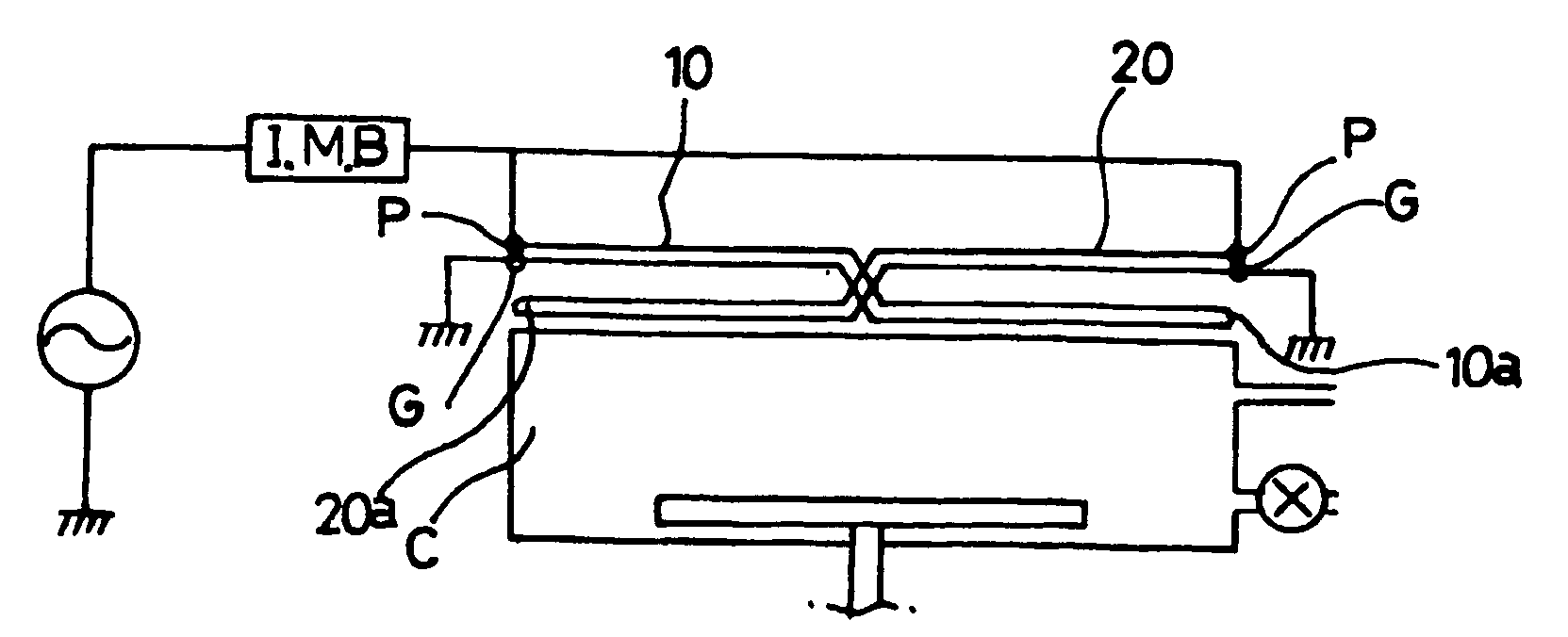
[0042]FIG. 7 is a perspective view of an antenna structure according to still another embodiment of the present invention, and FIG. 8 is a cross-sectional view of an inductively coupled plasma generator with the antenna structure shown in FIG. 7. The antenna structure according to this embodiment is installed in a cylindrical chamber, in which two antennas 10 and 20 coplanarly cross each other to be disposed at the interior and exterior, respectively, and the circuit thereof is the same as that of the present invention.

second embodiment

[0043]FIG. 9 is a perspective view of an antenna structure according to still another embodiment of the present invention, which is installed in a cylindrical chamber as shown in FIG. 8. Three antennas 10, 20 and 30 cross each other in three plies along the perimeters of three coplanar concentric circles, that is, the outermost circle 10, 20, 30, the intermediate circle 10b, 20b, 30b, and the innermost circle 10a, 20a, 30a, and have the same circuitry as those of the

[0044]FIG. 10 is a diagram showing the installation state of the antenna structure according to still another embodiment of the present invention. In this embodiment, parallel antennas A and B (or antennas shown in FIG. 3 or 6) installed across at the outer and inner parts of a flat dielectric member disposed above a chamber (not shown) are electrically connected to each other in parallel. In order to fabricate a large-diameter semiconductor, parallel antennas are concentrically arranged in two or three plies to make pla...


PUM

PropertyMeasurementUnit
sizeaaaaaaaaaa
frequencyaaaaaaaaaa
areaaaaaaaaaaa

Abstract

An antenna structure for an inductively coupled plasma generator suitable for processing large-diameter wafers or large, flat-panel display devices by making a plasma density distribution uniform and symmetrical with respect to a rotating direction inside a circular or rectangular chamber in which a wafer is processed. In the antenna structure having a powered end to which RF power is applied and a ground end connected to the ground, at least two loop antenna elements are disposed electrically in parallel with each other, the powered ends and ground ends of the respective antennas are disposed symmetrically with respect to the center of the antennas, and the antennas crossing each other such that the powered ends and ground ends thereof are disposed at a part far from a chamber and central parts thereof are disposed at a part close to the chamber.

Description

[0001]This application is a continuation of pending International Patent Application No. PCT / KR02 / 01407 filed Jul. 26, 2002 which designates the United States and claims priority of pending Korean Application No. 2001-23128 filed Jul. 30, 2001.FIELD OF INVENTION[0002]The present invention relates to an antenna structure for an inductively coupled plasma generator. More particularly, the present invention relates to an inductively coupled plasma generator in which impedance is reduced by using parallel antennas so as to uniformly adjust nonuniform plasma distribution density, which is due to high voltage application and nonuniformity in voltage throughout the antenna structure, the antennas being symmetrically installed and intersecting at their central parts where powered ends and ground ends thereof are disposed in parallel with each other, so that plasma is generated inside a chamber to be uniformly and symmetrically distributed with respect to a rotating direction.BACKGROUND OF I...

Claims


Application Information

Patent Timeline
Patent Type & Authority Patents(United States)
IPC IPC(8): H01Q21/00H01J7/24H01Q11/12H01J37/32H01L21/205H01L21/3065H05H1/46
CPCH05H1/46H01J37/321Y02E30/10C23C16/4401H01J37/3211
Inventor LEE, YOUNG-KWANLEE, SANG-WONUHM, SAE-HOON
Owner PLASMART CO LTD
Why Eureka
Try Eureka