Connector component for multi-core optical fiber, ferrule, and method for manufacturing the same

a multi-core, optical fiber technology, applied in the direction of optics, optical elements, instruments, etc., can solve the problems of difficult to increase productivity, difficult to use the above-mentioned optical connector in constructing a system, bad connections, etc., to improve the yield of metal ferrules for optical fibers as products, improve the wettability of the surface, and improve the mounting density of optical fibers

Inactive Publication Date: 2006-08-01
MUKOUDA TAKAHIKO
View PDF11 Cites 9 Cited by
  • Summary
  • Abstract
  • Description
  • Claims
  • Application Information

AI Technical Summary

Benefits of technology

[0050]Another aspect of the invention is a method of manufacturing a ferrule for a multi-core optical fiber, wherein the initial bubbles of said core wire are removed so as to improve the wettability of the surface, so that air holes are prevented from forming in the electrodeposited layer when manufacturing the ferrule.
[0051]More particularly, a method according to the present invention includes a step for electrodepositing metal around a core wire made of a metallic pipe whose inside diameter is, for example, 0.05 mm–0.13 mm, by electroforming in accordance with the diameter of an optical fiber, so as to form cylindrical material whose outside diameter is 1 mm or less. Also, when a metal ferrule for an optical fiber is manufactured by electroforming, a conductive core wire is used, and a stainless alloy (for example, SUS 304) pipe is used as the material for the core wire. For such a core wire, there can easily be obtained a core wire that (a) is manufactured by a protrusion method using dies or a wiring method, and (b) has an accuracy of being about 125.0 μm±0.5 μm in diameter.
[0052]According to the present invention, because the thickness of the metal to be electrodeposited around the core wire can be restrained to a required minimum value by making the diameter of the outer shape of the cylindrical material to be 1 mm or less, it bec...

Problems solved by technology

However, if the dimensional accuracy of the members that constitute this connector is not controlled strictly, the end faces of each fiber can cause displacement, resulting in bad connections.
Therefore, it has been impossible to use the above type of optical connector in constructing a system with a large optical-transmission path that has, for example, 1,000 channels.
However, such a manufacturing method has the following problems:(1) Because an expensive molding machine and a metallic mold are required for injection molding or protrusion molding, and because a metallic mold is susceptible to abrasion due to zirconia powder, the molding machine or the metallic mold must be constantly maintained or exchanged.(2) Because labor and special skills are required to use a diamond to grind the insertion holes, it is difficult to increase productivity.(3) Sintering at a high temperature requires much energy at enormous cost.(4) It is substantially impossible to create a plurality of insertion holes—into which optical fiber wires are to be inserted—on a sinter that is made of ceramic...

Method used


Image

  • Connector component for multi-core optical fiber, ferrule, and method for manufacturing the same
  • Connector component for multi-core optical fiber, ferrule, and method for manufacturing the same
  • Connector component for multi-core optical fiber, ferrule, and method for manufacturing the same

Examples


example 1

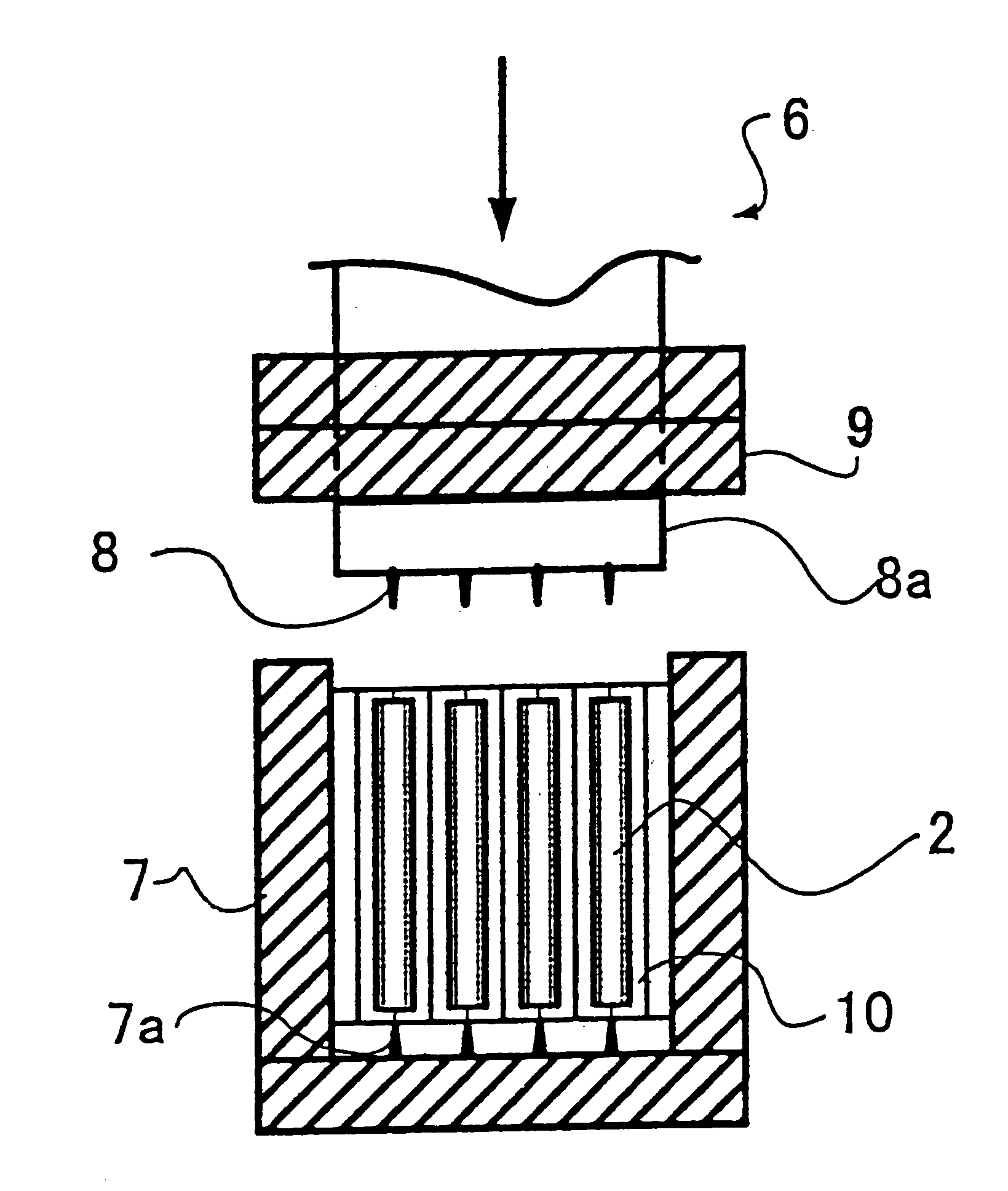
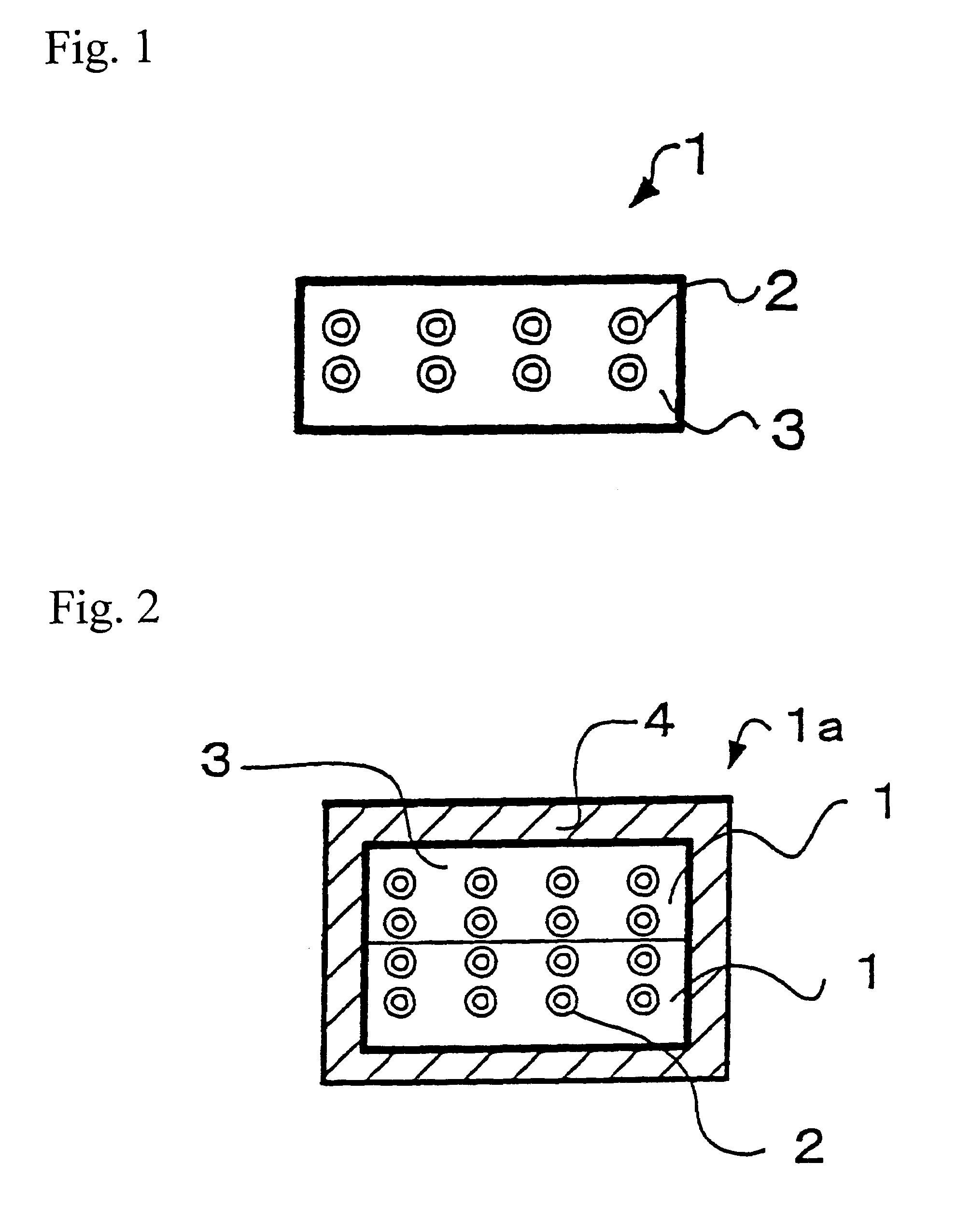
[0150]The surface-roughening agent to be used in thermal-spraying (product name: Sabnor; produced by Arc Techno Co., Ltd.), which is composed of epoxy resins, solvents, and curing agents, was sprayed onto the ferrules, which were fixed onto the positioning member by the method described for the above embodiment, so as to roughen the surface of each ferrule. The ferrules, which were formed into a specified shape, were coated on their surfaces (except for the sides having ferrule holes) by flame-spraying polyphenylenesulfide-base thermoplastic resin [FORTRON®; produced by Polyplastics Co., Ltd.], and each ferrule was formed into a specified shape, so that 20 connectors (each of which has 1 stage of ferrules in it) for 8-core optical fibers were manufactured.

[0151]At this time, the nozzle temperature was set at 300° C.–330° C., and the temperature near the ferrules was maintained at 150° C.–200° C. Measuring the eccentricity error (i.e., the error / difference between one ferrule hole's ...

example 2

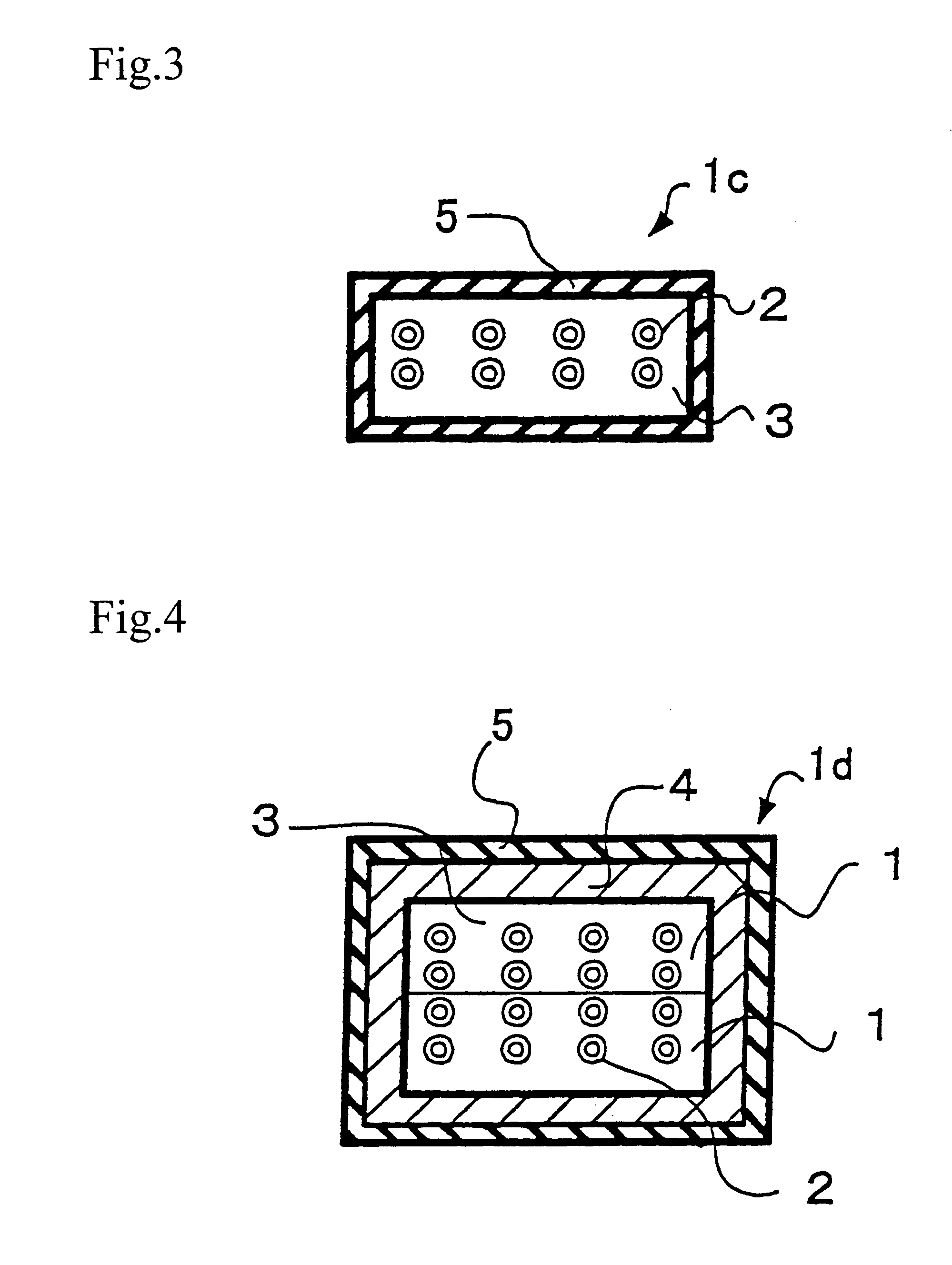
[0152]The surface-roughening agent for thermal-spraying (Sabnor; produced by Arc Techno Co., Ltd.), which is composed of epoxy resins, solvents, and curing agents, was sprayed onto the ferrules, which were fixed onto the positioning member by the method described for the above embodiment, so as to roughen the surface of each ferrule. The surfaces of the ferrules (except for the sides having ferrule holes), which were formed into a specified shape, were coated by arc-spraying zinc wire rods and aluminum wire rods [using the Arc Boy PC 120i low-temperature metal-spraying system; Arc Techno Co., Ltd.], and each ferrule was formed into a specified shape, so that 20 connectors (each of which has 2 stages of ferrules in it) for 8-core optical fibers were manufactured.

[0153]The temperature near the ferrules during thermal-spraying was maintained at 40° C.–50° C. Measuring the eccentricity error between the ferrule holes in the obtained connector for the 8-core optical fiber (after the conn...

example 3

[0154]The structures, which were obtained by cutting the connectors for optical fibers manufactured by the method of Example 2 into a specified shape and adjusting the positions of the ferrules' insertion holes and the wall surface, were piled up. They were then coated by flame-spraying IDEMITSU PPS onto their surfaces (except for the sides having ferrules holes), and each ferrule was formed into a specified shape, so that 10 connectors (each of which has 4 stages of ferrules in it) for 16-core optical fibers were manufactured.

[0155]At this time, the nozzle temperature was set at 300° C.–330° C., and the temperature near the ferrules was adjusted to 150° C.–200° C. Measuring the eccentricity error between the ferrule holes in the obtained connector for the 16-core optical fiber (after the connector was formed into a specified shape) revealed that the error range was ±0.05 μm–0.5 μm.


PUM

PropertyMeasurementUnit
Currentaaaaaaaaaa
Shapeaaaaaaaaaa

Abstract

The objective is to offer a connector component for multi-core optical fiber, or an assembly of ferrules, having high precision ferrules in concentricity, circularity, axial linearity, and spacing distance, as well as to offer a method of manufacturing the same at a reduced cost. The connector (or ferrules) is featured by its manufacturing method including thermal-spraying or electroforming is applied, using a resin or a metal, to a plurality of cylinder-shaped ferrules, under the condition that projections which are positioned opposite each other of a positioning member are fitted and nipped to both ends of insertion holes of the cylinder-shaped ferrules so that each ferrule is properly positioned and the central axes are parallel to each other at specified positions so that the plurality of cylinder-shaped ferrules are coated.

Description

DETAILED DESCRIPTION OF THE INVENTION[0001]1. Field of the Invention[0002]The present invention relates to a connector used to connect multi-core optical fibers, and more particularly to (a) a connector wherein the connection ends of the linked optical fibers are arranged in a two-dimensional manner, and (b) a method of manufacturing said connector.[0003]2. Description of the Related Art[0004]Recently, a communication means using optical-fiber cable has been developed for transmitting and receiving a large volume of diverse information at one time, and the demand for optical connectors to connect various pieces of equipment, devices, and optical-circuit parts in optical-communications systems or optical-application measuring systems has been increasing.[0005]Optical fiber is mainly composed of quartz glass, and it consists of a core part, to which light power is concentrated, and a clad part that confines the light power. Because the age of multimedia has begun, optical fibers are b...

Claims


Application Information

Patent Timeline
IPC IPC(8): G02B6/36C25D1/02C25D2/00G02B6/38
CPCG02B6/3833G02B6/3865G02B6/3644G02B6/3672G02B6/3878G02B6/3684G02B6/40
Inventor MUKOUDA, TAKAHIKO
Owner MUKOUDA TAKAHIKO
Why Eureka
Try Eureka