UV-blocking etch stop layer for reducing UV-induced charging of charge storage layer in memory devices in BEOL processing
- Summary
- Abstract
- Description
- Claims
- Application Information
AI Technical Summary
Benefits of technology
Problems solved by technology
Method used
Image
Examples
Embodiment Construction
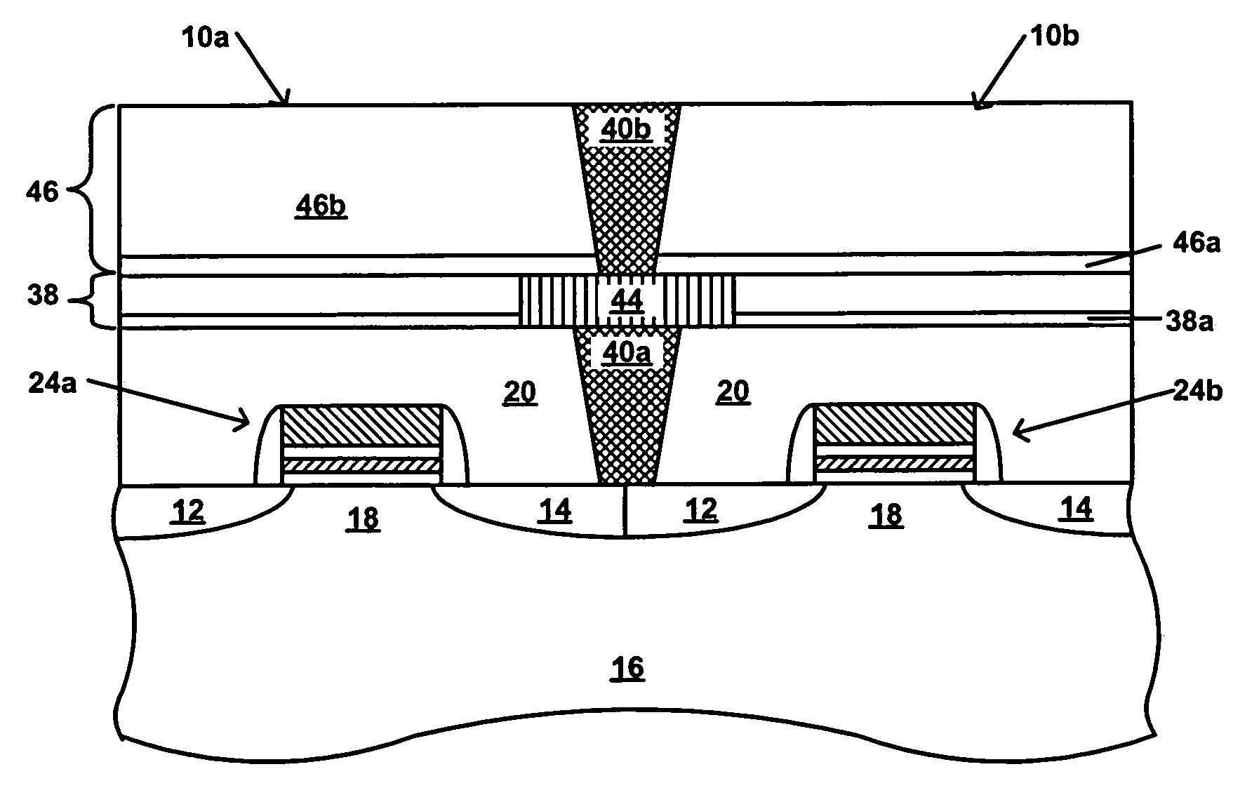
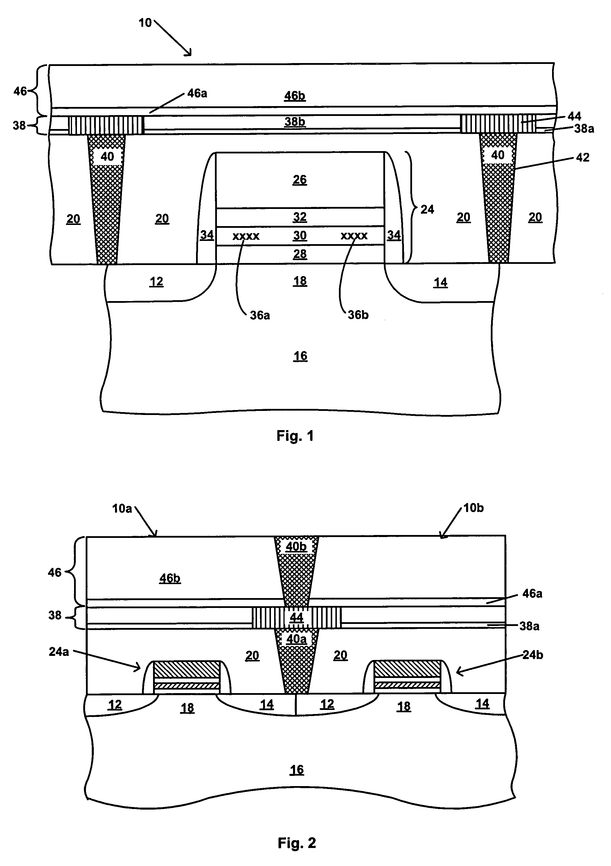
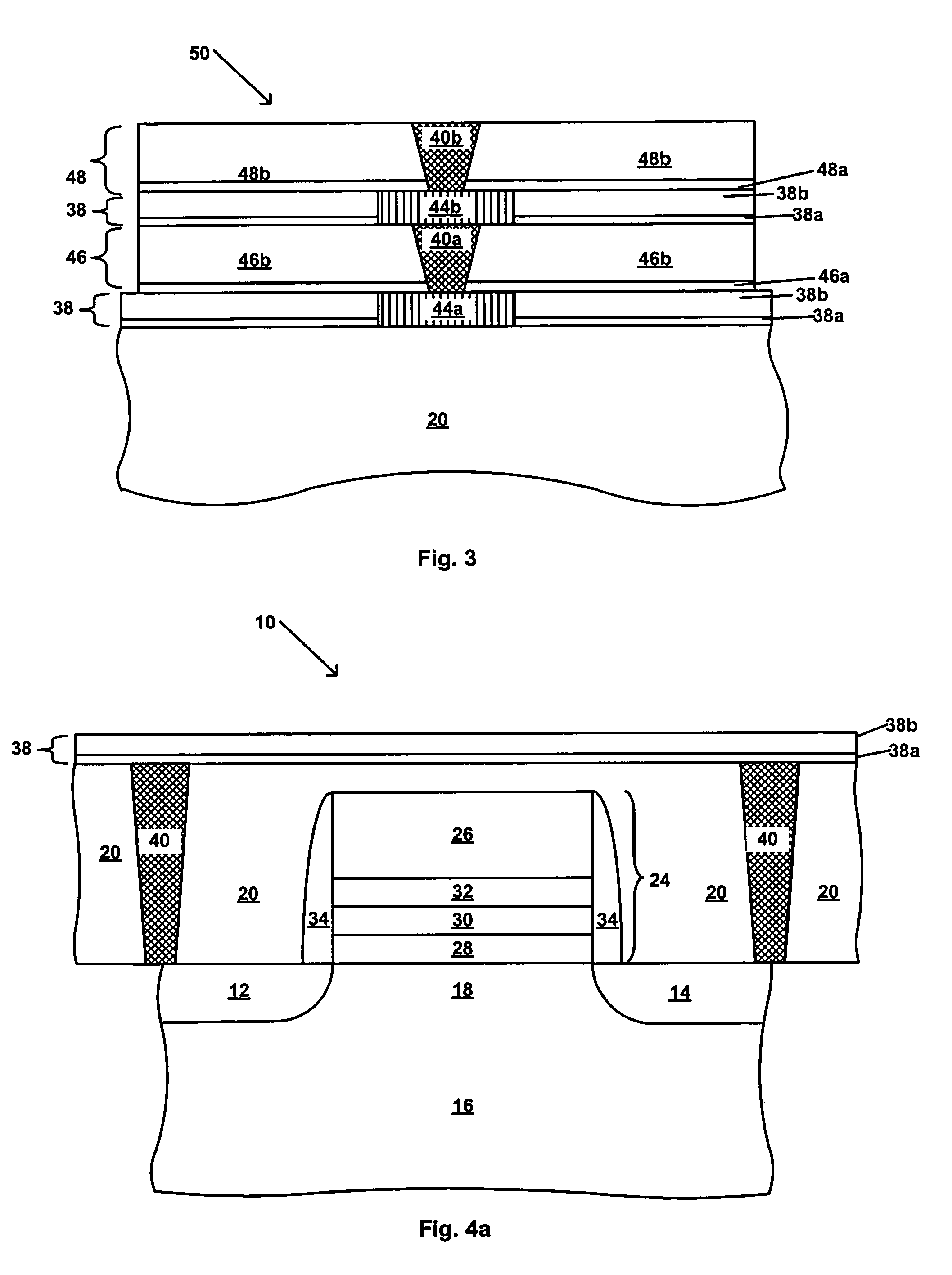
[0026]Referring first to FIG. 1, there is schematically shown in cross-section a transistor 10, which in one embodiment is a charge trapping dielectric flash memory cell, suitable for use in a dual-bit EEPROM device, such as the MIRRORBIT™. The transistor 10 includes source / drain regions 12 and 14 located in a semiconductor substrate 16 and separated by a channel region 18. The substrate 16 may be, for example, a single crystal silicon wafer. The substrate 16 may also be gallium arsenide, a silicon-on-insulator layer, an epitaxial layer, a silicon-germanium layer, a germanium-on-insulator layer, or other known semiconductor substrate. A stack gate 24 overlies the channel region 18. The stack gate 24 includes a control gate electrode 26, and an ONO structure including a bottom or tunnel oxide layer 28, a charge storage layer 30 and a top oxide layer 32, as shown in FIG. 1. In one embodiment, the charge storage layer 30 is a nitride containing charge storage layer. In one embodiment, ...
PUM
 Abstract
Description
Claims
Application Information
 - R&D
- Intellectual Property
- Life Sciences
- Materials
- Tech Scout
- Unparalleled Data Quality
- Higher Quality Content
- 60% Fewer Hallucinations
Browse by: Latest US Patents, China's latest patents, Technical Efficacy Thesaurus, Application Domain, Technology Topic, Popular Technical Reports.
© 2025 PatSnap. All rights reserved.Legal|Privacy policy|Modern Slavery Act Transparency Statement|Sitemap|About US| Contact US: help@patsnap.com


