
Architecture for wireless transmission of high rate optical signals

a wireless transmission and optical signal technology, applied in wireless communication, line-of-sight transmission, wireless communication, etc., can solve the problems of reducing the service life of the device, and reducing the cost of the device, so as to minimize intersymbol interference and low noise

Inactive Publication Date: 2006-09-05
OL SECURITY LIABILITY CO
View PDF1 Cites 58 Cited by
  • Summary
  • Abstract
  • Description
  • Claims
  • Application Information

AI Technical Summary

Benefits of technology

[0005]This approach provides several advantages over prior art systems. Most significantly, there is no processing of baseband protocol information in the received optical signal—only the raw data rate signal is extracted. Thus, the extracted signal may retain its modulation encoding such as Code Division Multiple Access (CDMA), Time Division Multiple Access (TDMA), or other carrier network specific protocol encoding. The converter will therefore work appropriately regardless of how the input data stream was encoded. The synchronous data stream of any protocol can therefore be detected, even those that use proprietary protocol encoding. The radio transmission is therefore accomplished without knowledge of the format of the particular incoming signal.
[0007]A Quadrature Phase Shift Keying (QPSK) modulator then modulates each symbol as a phase state in a microwave oscillator output. After the QPSK signal has been encoded and modulated in this fashion, it is then filtered to minimize its output bandwidth. This filter, when combined with other output Radio Frequency (RF) filters, has as a preferred cosine roll-off over frequency. By filtering out low frequencies relative to the ultimate output microwave carrier frequency, the percent bandwidth of the filter passband is maximized. The group delay of the filters in the chain should also be minimized to reduce intersymbol interference.
[0008]Once the signal is filtered, it is up-converted to a microwave carrier in the V-band using a fundamental mixer. A fundamental mixer frequency output filter is then used to reject the local oscillator image or any other image frequencies. A Monolithic Microwave Integrated Circuit (MMIC) amplifier can boost the power level of the resulting signal, before it is fed to an output diplexer.
[0010]The companion unit receives the radiated microwave signal from the transmitting unit, passing it through the receiver side of the diplexer into a Low Noise Amplifier (LNA). The LNA output is then fed to an image reject filter. A mixer, which may be a harmonic mixer, is used to convert the received signal to a lower frequency (IF) signal. The receiver filter can also preferably be implemented with a cosine roll-off to minimize intersymbol interference.
[0011]After IF filtering, the received signal is demodulated by a noncoherent differential QPSK demodulator to recover the transmitted bit stream. Demodulation of in-phase (I) information is accomplished by delaying the received signal by one symbol minus 45 degrees and then mixing it with the undelayed received signal. The quadrature phase (Q) information is recovered by delaying the received signal by one symbol plus 45 degrees and then mixing it with the undelayed received signal. This noncoherent method of demodulation recovers both I and Q components of the transmitted signal without having to recover the carrier of the modulated signal, and without introducing ambiguities. By avoiding carrier recovery, this demodulator is therefore tolerant to frequency offset and phase noise from the transmitter modulated carrier, as well as from the V-band local oscillator used for up-conversion in the transmitter and down conversion in the receiver.

Problems solved by technology

In practice, the required operating parameters for such a device have been relatively difficult to achieve.
Unfortunately, existing designs are relatively limited in their ability to meet all of these performance criteria at reasonable cost.

Method used


Image

  • Architecture for wireless transmission of high rate optical signals
  • Architecture for wireless transmission of high rate optical signals
  • Architecture for wireless transmission of high rate optical signals

Examples


Embodiment Construction

[0024]A description of preferred embodiments of the invention follows.

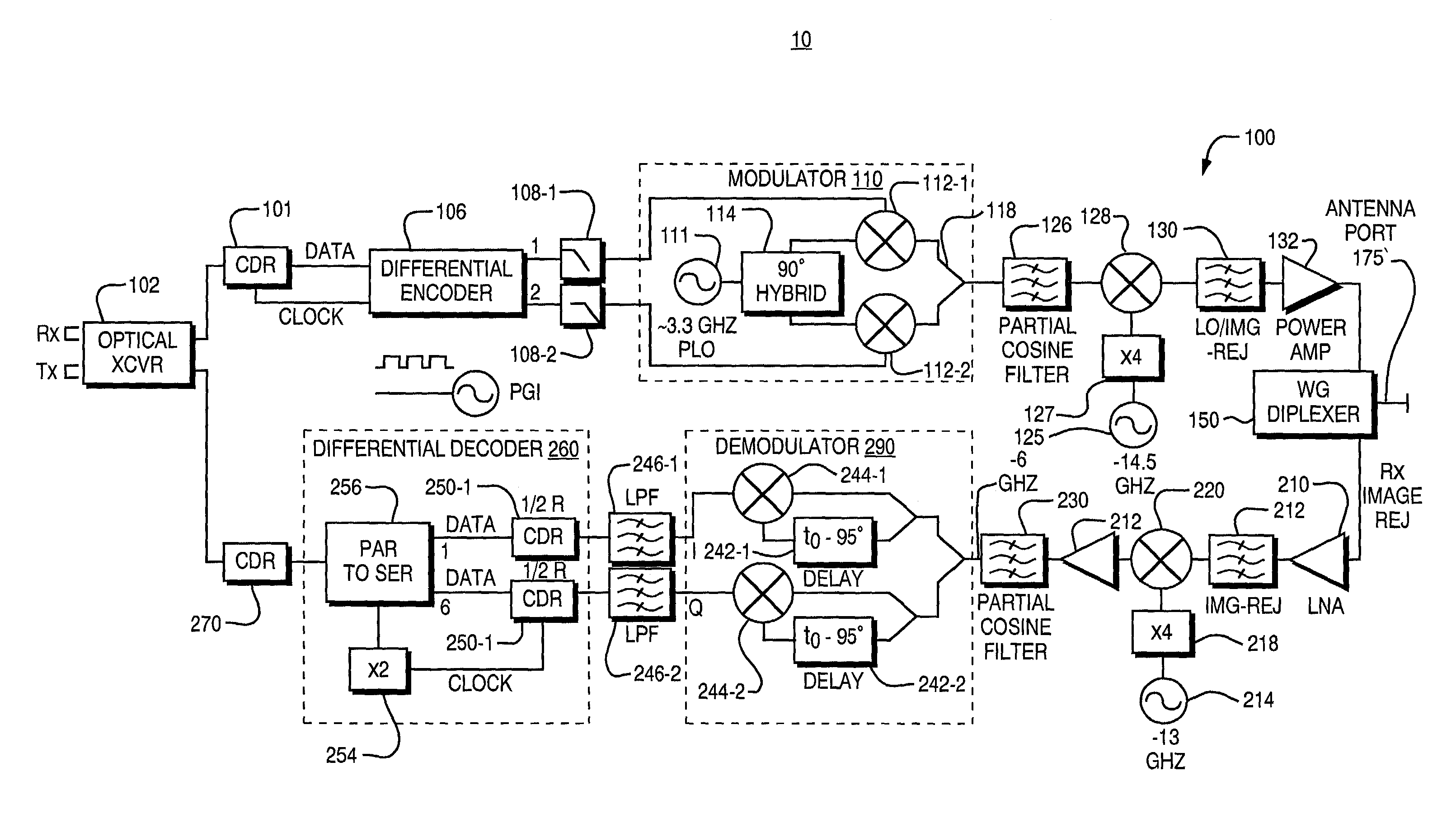
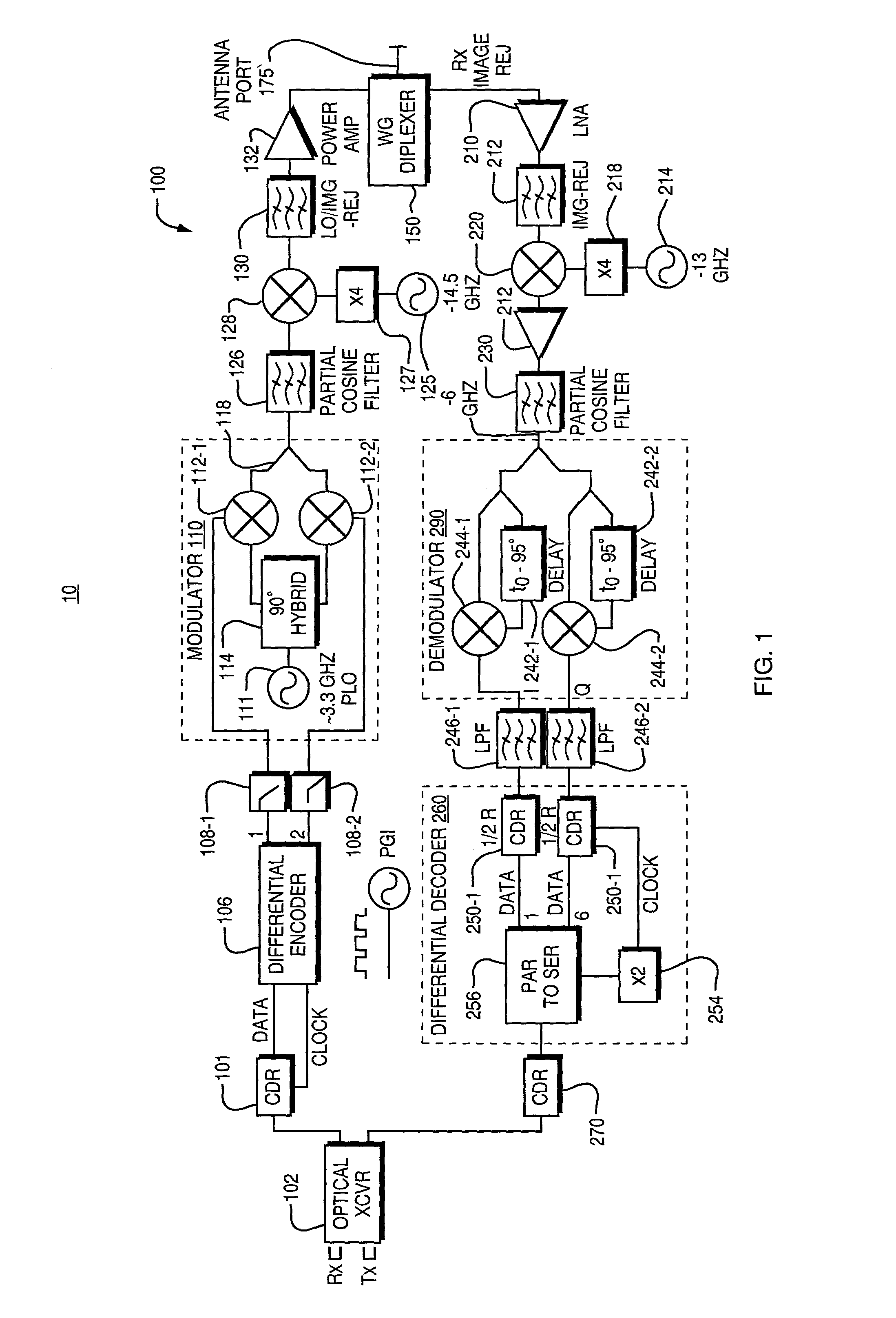
[0025]FIG. 1 is a block diagram of an optical to wireless microwave signal converter 10 according to the invention. The converter 10 includes an optical to electrical or microwave transmitter portion 100 and an electrical to optical or microwave receiver portion 200. It should be understood that in a typical point to point system, there will be two converters 10, each associated with one of two end points of a communication link.

[0026]The microwave transmitter portion 100 uses an optical transceiver 102 to receive an input optical signal. The optical signal is a high data rate protocol encoded signal such as a SONET signal. It should be understood that other types of optical transport signals such as Gigabit Ethernet (GE) signals may be converted to microwave signals using the principles of the present invention. The optical transceiver converts the optical signal to an electric signal, which in turn is fed to a C...


PUM


Abstract

An apparatus for a wireless transmission of high data rate signals such as received from an optical interface including gigabit fiber channel or a sonet. The architecture combines direct detection of the optical signal with clock and data recovery circuit and a differential signal encoder which is preferably a differential quadrature phase shift encoder and modulator pair. A millimeter wave, local oscillator and up conversion chain converts the optical input signal to a microwave carrier. In the opposite direction, the down converted signal is non-coherently phase detected and fed to a pair of synchronized clock and data recovery circuits to recover I and Q channel signals. These recovered signals are then combined prior to re-timing before they are fed back to the optical transceiver.

Description

BACKGROUND OF THE INVENTION[0001]Point to point, fixed, wireless signaling technologies that operate in unlicensed microwave radio frequency bands have recently received increased attention. From a regulatory perspective, the radio spectrum at 40 GigaHertz (GHz) and above is relatively interference-free. The ability to form very narrow radiation beams at these frequencies with physically small apertures also minimizes interference between adjacent users.[0002]These technologies are expected to enable high speed, low cost access to data networks in remote locations as well as in urban and metropolitan areas. Because of the inherent broadband nature of these connections, they may be typically used to facilitate other high speed services, such as video on demand. Equipment operating in this band is also expected to be applied to backhaul or aggregation of secondary networks such as lower frequency wireless networks, Local Multipoint Distribution Service (LMDS), cable facilities, cellul...

Claims


Application Information

Patent Timeline
IPC IPC(8): H04B10/00
CPCH04B10/112
Inventor KOH, CHRISTOPHER T.ROBINSON, WYLEYLEE, MYUNG K.HOLZMAN, ERIC L.PERGOLA, KENNETH MICHAEL
Owner OL SECURITY LIABILITY CO
Learn More