Optical receiver

a receiver and optical technology, applied in the field of optical receivers, can solve the problems of minuscule gap between the filter and the light-transmitting medium, and achieve the effect of stabilizing the performance of the optical receiver, small in size, and few in number

Active Publication Date: 2006-09-12
SUMITOMO ELECTRIC IND LTD
View PDF6 Cites 24 Cited by
  • Summary
  • Abstract
  • Description
  • Claims
  • Application Information

AI Technical Summary

Benefits of technology

[0020]The present invention has a feature in that a wavelength-selecting filter is attached intimately to the end face of or to a cut section at a midpoint of a light-transmitting medium such as an optical fiber or waveguide that introduces incoming light. Light having passed through the filter is introduced to a PD. This method gives wavelength selectivity to a surface-mounted optical receiver. Since the filter is in intimate contact with the end face of or with a cut section of a light-transmitting medium, it can select the assigned wavelength while the beam of light practically remains parallel. This method stabilizes the performance of the optical receiver. Therefore, it is not necessary to rely on a collimator, an inverse collimator, and a lens. Consequently, the present invention can offer an optical receiver small in size, few in the number of parts, simple in assembly, and, above all, low in cost.

Problems solved by technology

Although the wavelength-selecting filter is in intimate contact with the end face of or with a cut section of a light-transmitting medium, a minuscule gap between the filter and the light-transmitting medium cannot be avoided.

Method used


Image

  • Optical receiver
  • Optical receiver
  • Optical receiver

Examples


embodiment 1

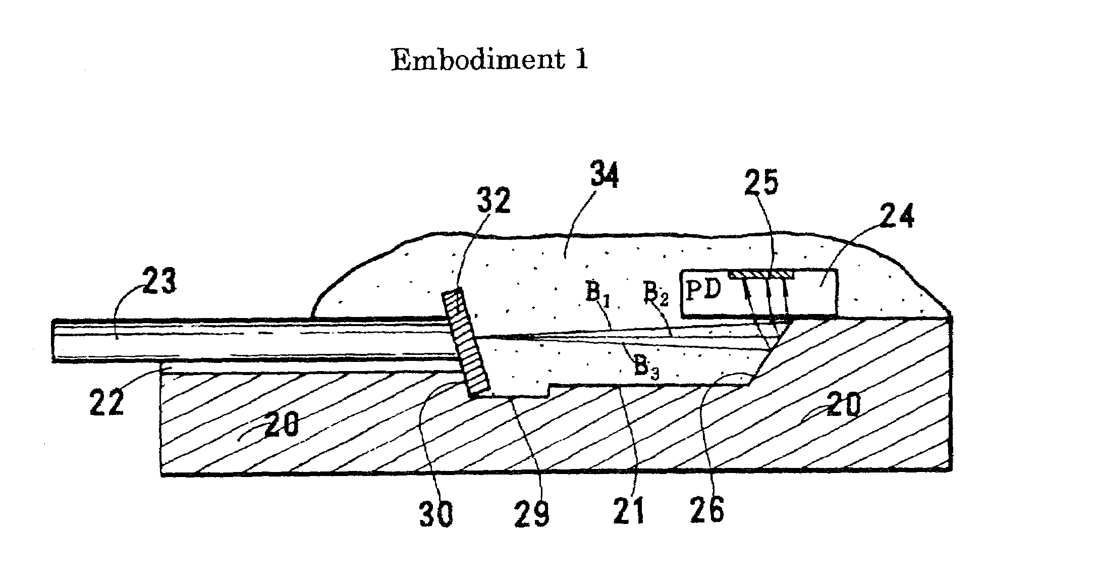
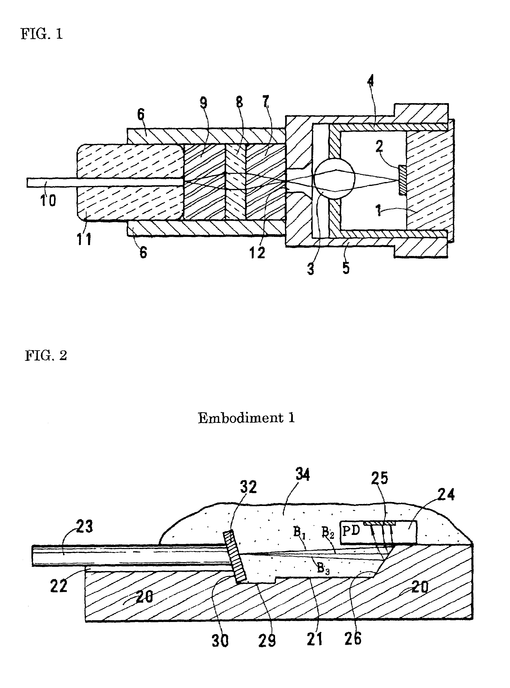
[0071]FIGS. 2 and 3 show an optical receiver of Embodiment 1 of the present invention. An optical pathway-changing groove 21 and a V-shaped groove 22 are provided on the top of an Si substrate 20, which has the shape of a rectangular solid. The V-shaped groove 22 is provided from the front end to the center portion of the substrate, and the optical pathway-changing groove 21 from the center portion to the middle portion of the rear half. They are provided on the center axis of the substrate and are separated by a lateral groove 29. An optical fiber 23 is placed in the V-shaped groove 22 and fixed there. The V-shaped groove 22 eliminates the need for the alignment work of the optical fiber. The V-shaped groove 22 can be formed by anisotropic etching. It can also be formed by a mechanical means. The lateral groove 29, can also be formed by either etching or a mechanical means.

[0072]Although not shown in the figures, an electrode pattern is printed by metallizing on the Si substrate 20...

embodiment 2

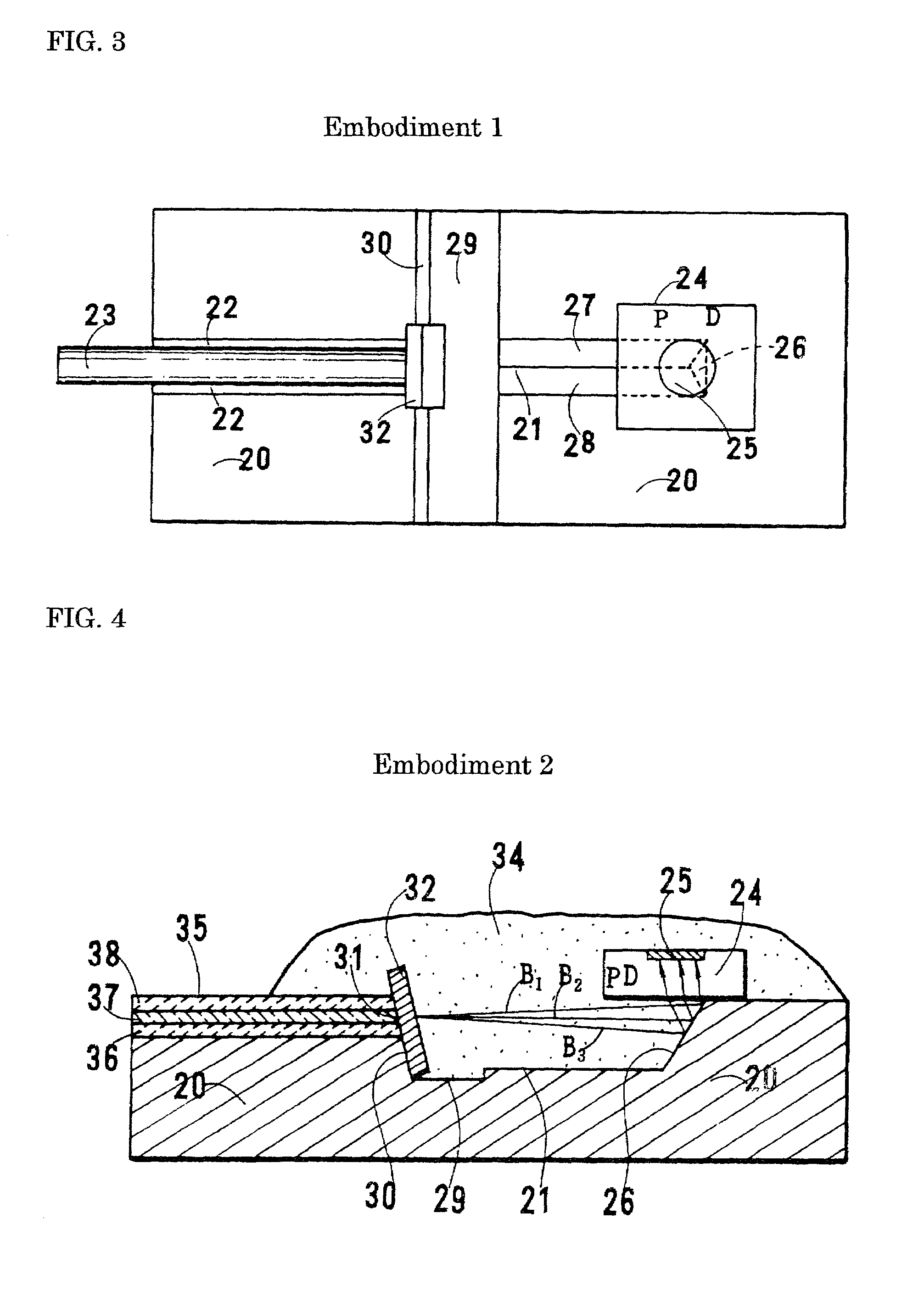
[0087]FIGS. 4 and 5 show Embodiment 2. Dissimilar to Embodiment 1, an SiO2-based optical waveguide is formed on the Si substrate in place of the optical fiber, and the wavelength-selecting filter is cemented to the end face of the waveguide. Since no optical fiber is used, no V-shaped groove is required. Consequently, no optical fiber-fixing work is required.

[0088]An optical pathway-changing groove 21 is provided on the center axis of an Si substrate 20, which has the shape of a rectangular solid. The optical pathway-changing groove 21, provided at the middle portion of the substrate, has three faces: an oblique end face 26 and side faces 27 and 28. These faces are coated with gold, aluminum, or another material to increase the reflectance. A PD 24 is mounted directly above the oblique end face 26. The PD is also a back-illuminated type. A top-illuminated PD may be used by mounting it upside down.

[0089]A waveguide 35 is formed from the front end to the center portion of the Si subst...

embodiment 3

[0093]FIGS. 6 and 7 show Embodiment 3. As is the case with Embodiment 1, a V-shaped groove is provided on an Si substrate to fix an optical fiber. An oblique space is provided at the midpoint of the optical fiber, and a wavelength-selecting filter is inserted into the space.

[0094]An optical pathway-changing groove 21 and a V-shaped groove 22 are provided on the center axis of a substrate 20, which has the shape of a rectangular solid. The optical pathway-changing groove 21 is coated with metal to increase the reflectance. A PD 24 is mounted directly above the oblique end face 26. An optical fiber 23 is placed in the V-shaped groove 22 formed from the front end to the center portion of the substrate and fixed there. The end face of the optical fiber is obliquely polished to prevent the reflected light from returning to an LD. An oblique wavelength selecting filter-fixing groove 39 is provided by cutting orthogonally to the axis of the optical fiber at the midpoint of the optical fibe...


PUM


Abstract

An optical receiver, small and inexpensive, is used for a WDM transmission system in place of a wavelength demultiplexer. In the receiver, a light-transmitting medium and a photodiode (PD) are placed on the same substrate, a wavelength-selecting filter is attached perpendicularly or obliquely to the end face of or to a cut section at the midpoint of the medium, the filter transmits only the assigned wavelength included in the incident light having multiplexed wavelengths, and the PD detects only the assigned wavelength. With an optical fiber, the fiber can be housed in a ferrule. In this case, the filter is inserted into a filter-supporting hole provided at a midpoint of the ferrule, the ferrule is fixed in a groove formed on the substrate, and an optical pathway-changing groove formed on the substrate reflects light having emerged from the optical fiber to introduce it into the PD.

Description

BACKGROUND OF THE INVENTION[0001]1. Field of the Invention[0002]The present invention relates to an optical receiver for an optical communication system, particularly an optical receiver that can be used advantageously in an optical wavelength division multiplexing (WDM) communication system that transmits signals by using light having a plurality of different wavelengths.[0003]2. Description of the Background Art[0004]As optical communication systems become prevalent in the world, they have been increasingly incorporating WDM transmission systems that use a plurality of wavelengths in order to further increase the capacity of communication. In particular, researchers and engineers have been studying a system that connects a central office and subscribers by using a plurality of wavelengths, for example from four to sixteen wavelengths, in order to introduce optical fibers into the subscribers' lines at low cost.[0005]In this case, a high-performance wavelength multiplexer is placed...

Claims


Application Information

Patent Timeline
Patent Type & Authority Patents(United States)
IPC IPC(8): G02B6/42G01J1/04G02B6/00G02B6/34H01L31/0232
CPCG02B6/12007H04B10/60G02B6/42G02B6/4204G02B6/4214G02B6/4246H01L31/0203G01J1/0204G01J1/0209G01J1/0414G01J1/0488G02B6/29361H01L2224/48091H01L2224/48137H01L2224/48247H01L2224/49171G02B6/4253G02B6/4215G02B6/424G02B6/4265H01L2924/00014
Inventor NAKANISHI, HIROMIYAMABAYASHI, NAOYUKIKUHARA, YOSHIKI
Owner SUMITOMO ELECTRIC IND LTD
Why Eureka
Try Eureka