
Gaussian frequency shift keying digital demodulator

Active Publication Date: 2006-09-19
TEXAS INSTR INC
View PDF5 Cites 16 Cited by
  • Summary
  • Abstract
  • Description
  • Claims
  • Application Information

AI Technical Summary

Benefits of technology

[0017]Several advantages of the digital demodulator of the present invention include the ability to be implemented in a very small size, and therefore low cost, compared with prior art solutions. In addition, the mechanism is operative to extract actual phase differences wherein frequency offsets are translated to DC offsets, thereby greatly simplifying frequency offset compensation in subsequent processing. This is in comparison to prior art differential demodulators which typically generate the sine, cosine or other nonlinear function of the phase difference, which greatly complicates frequency offset estimation and compensation resulting in either added complexity or degraded performance for certain values of frequency offsets.
[0018]Another advantage of the mechanism of the present invention is that phase extraction is operative to generate signals with linear noise terms. This is in contrast to prior art solutions wherein the resultant noise terms are nonlinear and correlated to the data due the multiplications typically performed. Linearity of the noise in the presence of intersymbol interference (ISI) serves to simplify the realization of equalizers placed after the demodulator and provide enhanced performance.
[0019]A further advantage of the mechanism is that the it enables subsequent frequency offset compensation that can be implemented very simply and which can be performed in a feed forward manner without requiring a closed loop architecture. Since frequency offsets are translated into DC offsets, the frequency offsets are easier to extract and suppress as compared to prior art cross-multiply architectures typically used for digital demodulation, which have the disadvantage of introducing distortion when frequency offsets are present.

Problems solved by technology

In digital communications systems, a carrier signal is modulated with the digital data to be transmitted over the channel, where it typically suffers various forms of distortion, such as additive noise.
First, the Bluetooth specification permits a frequency error of up to 75 kHz in the transmitted signal.
Second, the Bluetooth specification also permits up to 20 ppm of frequency inaccuracy in the receiver crystal reference, which could result in up to 50 kHz of frequency offset in the receiver's local oscillator which is used in the downconversion.
Lastly, an additional 15 kHz of frequency offset may be due to clock jitter caused by using clocks derived from dividing the master local clock signal, wherein the local clock signal is hopping from frequency to frequency resulting in jitter.
Note that using a lower modulation index of 0.28, which the Bluetooth specification allows, makes the problem even worse.

Method used


Image

  • Gaussian frequency shift keying digital demodulator
  • Gaussian frequency shift keying digital demodulator
  • Gaussian frequency shift keying digital demodulator

Examples


Embodiment Construction

Notation Used Throughout

[0036]The following notation is used throughout this document.

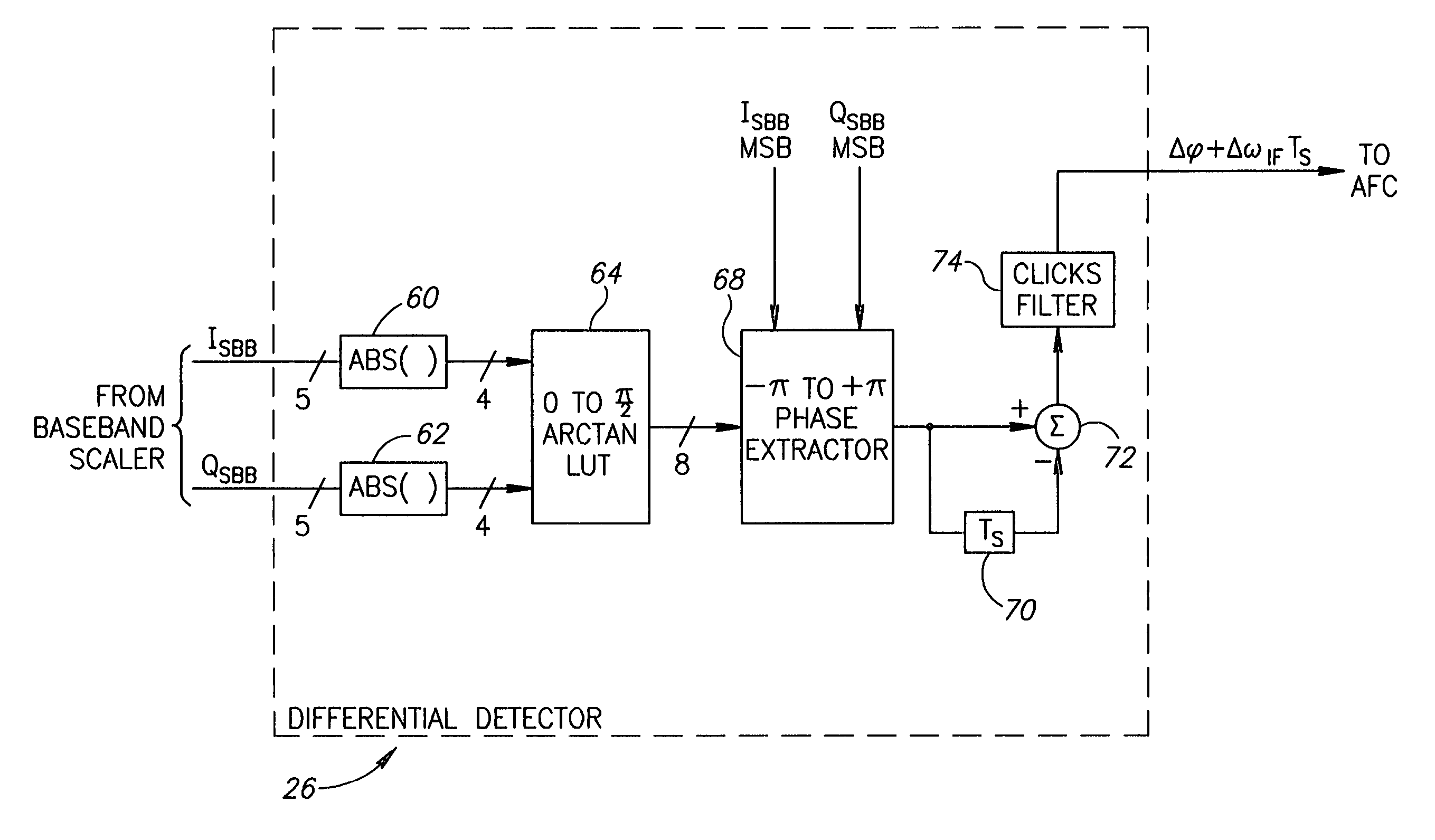
[0037]

TermDefinitionAFCAutomatic Frequency ControlAHDLAdaptive Hard Decision LogicASICApplication Specific Integrated CircuitAWGNAdditive White Gaussian NoiseBERBit Error RateDCDirect CurrentFPGAField Programmable Gate ArrayFSKFrequency Shift KeyingGFSKGaussian Frequency Shift KeyingHDLHardware Description LanguageIFIntermediate FrequencyISIIntersymbol InterferenceLOLocal OscillatorLSBLeast Significant BitLUTLook-Up TableMSBMost Significant BitRAMRandom Access MemoryROMRead Only MemoryRFRadio Frequency

Detailed Description of the Invention

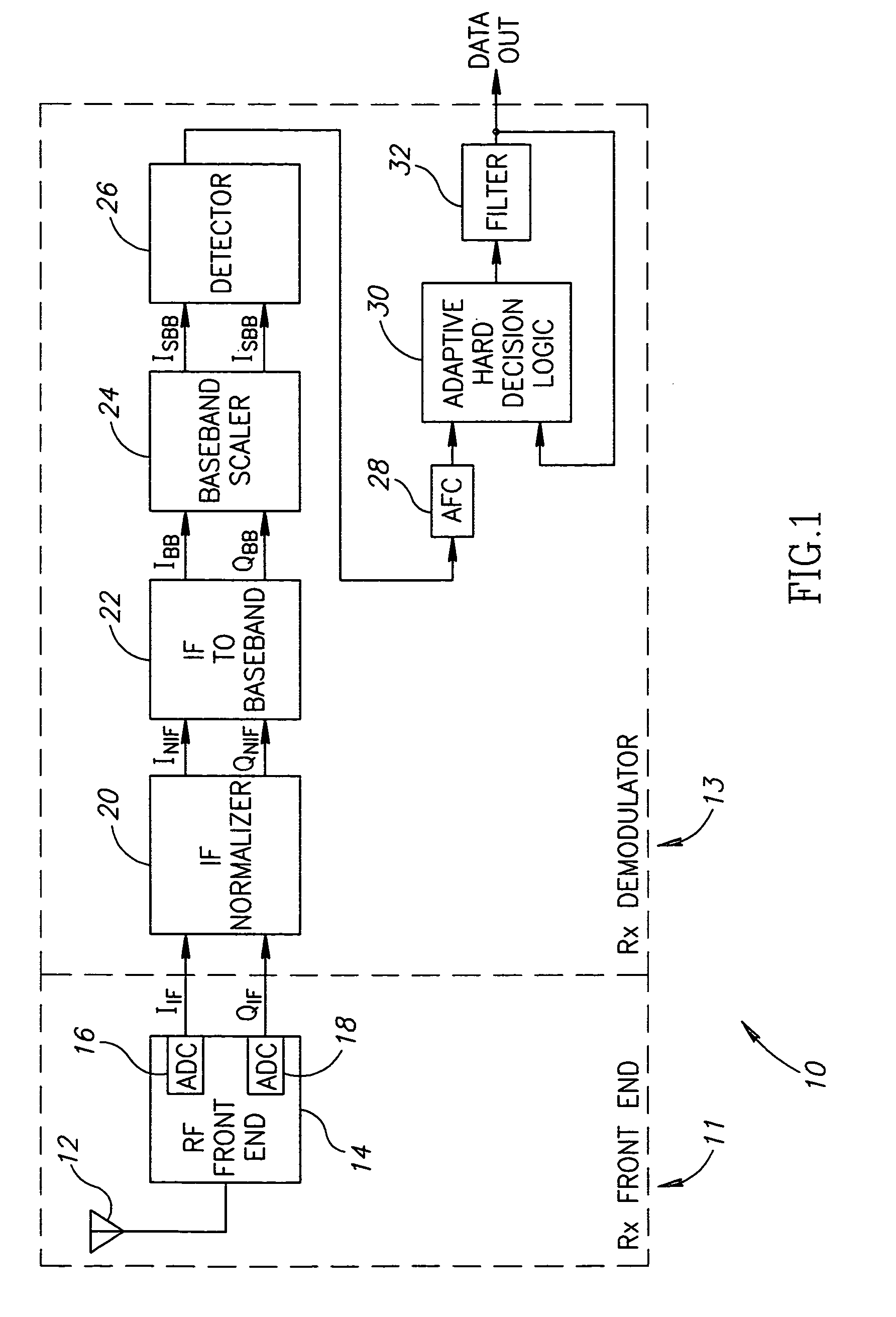
[0038]The mechanism of the present invention is based on extracting phase differences directly from the I and Q signals after downconversion to zero-IF and image rejection are performed. The phase Φ represented by the quadrature I and Q signals is determined using the relationship

[0039]φ=arctan⁡(QI).

A lookup table stores the values of the arctan function preferably...


PUM


Abstract

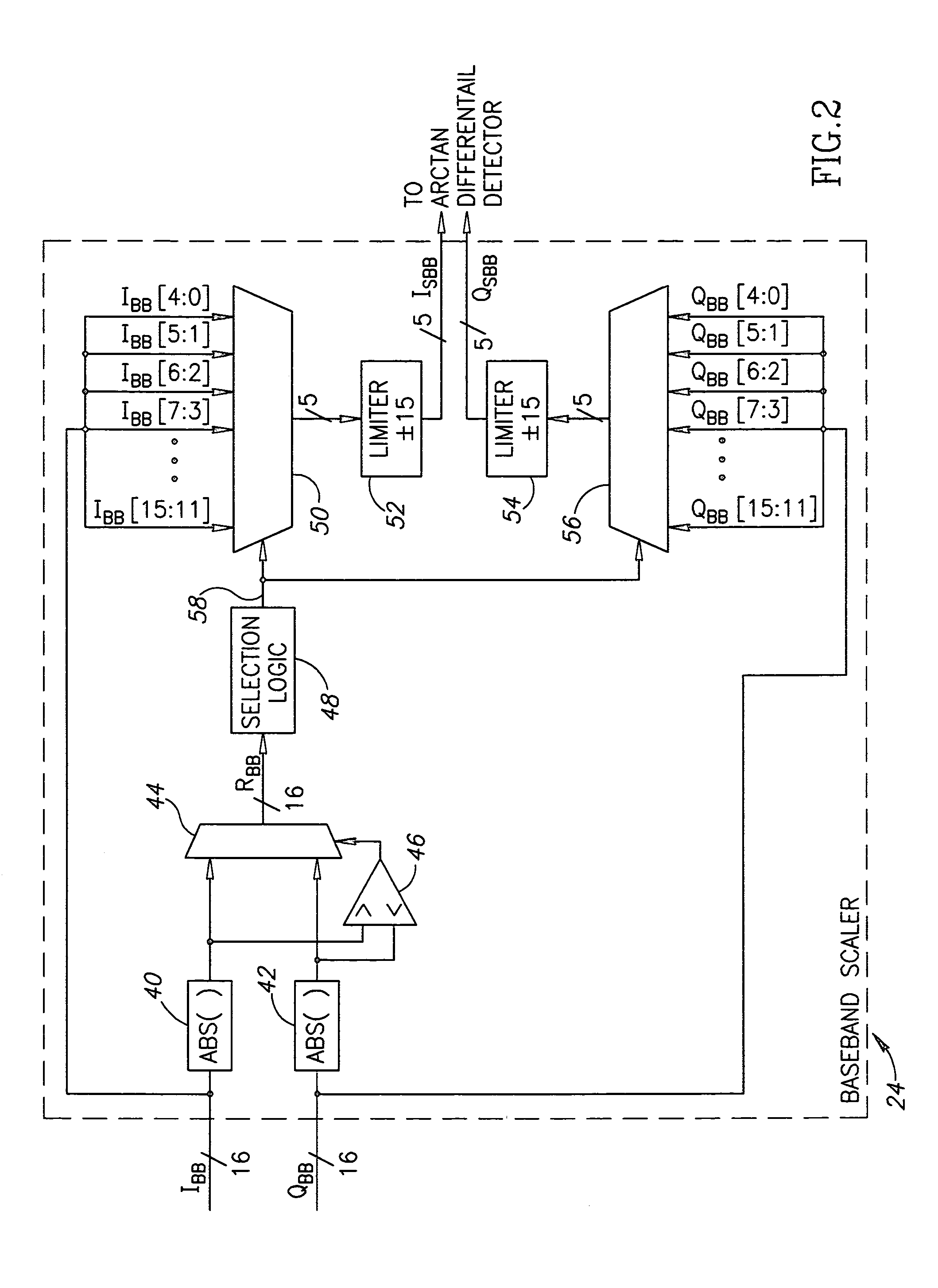
A digital demodulator employing a digital differential detection mechanism based on extracting phase differences directly from the I and Q signals after downconversion to zero-IF and image rejection are performed. The phase of the input I and Q signals is determined using the principle that the phase is equivalent to arctan(QI).A lookup table stores the values of the arctan function preferably in a reduced size format. The size of the lookup table can be reduced significantly by storing arctan values for the first quadrant only (i.e. 0 to 90°) and taking advantage of the fact that the phase values for the other three quadrants can be derived from those of the first with some correction applied depending on the signs of the I and Q input samples. Phase extraction logic is provided that is operative to map the phase into the entire 0 to 360° range of phase values (i.e. −π to +π radians) based on the signs of the I and Q signals. The phase difference between a current phase value and the previous phase value is then calculated. It is these phase differences that reflect the frequency deviations present in the transmitted signal which represent the original modulating signal. A ‘click’ removal filter circuit is provided to remove the discontinuities in the phase difference output that occur when the 2π radians value is crossed.

Description

REFERENCE TO RELATED APPLICATIONS[0001]This application is based on U.S. Provisional application Ser. No. 60 / 466,684, filed Apr. 29, 2003, entitled “GFSK Digital Demodulator for Bluetooth”, incorporated herein by reference in its entirety.FIELD OF THE INVENTION[0002]The present invention relates to the field of data communications and more particularly relates to a digital demodulator for use in a digital Gaussian frequency shift keying (GFSK) receiver such as a receiver constructed according to the Bluetooth standard.BACKGROUND OF THE INVENTION[0003]In digital communications systems, a carrier signal is modulated with the digital data to be transmitted over the channel, where it typically suffers various forms of distortion, such as additive noise. The digital data is often transmitted in bursts wherein each burst consists of a number of data bits. Upon reception, the signal must be demodulated in order to recover the transmitted data.[0004]It is common for receivers to employ dire...

Claims


Application Information

Patent Timeline
IPC IPC(8): H04L27/14H03D3/00H04L27/20
CPCH04L27/205H04L27/2032
Inventor SUISSA, UDIELIEZER, OREN
Owner TEXAS INSTR INC
Learn More