Optical displacement sensor using optical fiber, and external force detecting device

a technology of optical fiber and displacement sensor, applied in the direction of optical radiation measurement, photometry using electric radiation detector, instruments, etc., can solve the problems of high processing accuracy, increased electric power consumption, and increased cost as well as an increase in so as to reduce the number of components, reduce power consumption, and enhance the effect of displacement detection

Inactive Publication Date: 2006-10-17
MINEBEA CO LTD
View PDF3 Cites 7 Cited by
  • Summary
  • Abstract
  • Description
  • Claims
  • Application Information

AI Technical Summary

Benefits of technology

[0013]The present invention has been made in view of the above problems, and it is an object of the present invention to provide a six-axis force sensor, in which the diameter of a light beam can be controlled and a uniform intensity distribution of emitted light can be secured without providing a pinhole aperture structure.
[0014]In order to achieve the above object, according to a first aspect of the present invention, an optical displacement sensor comprises: a light source disposed at one of a reference object and a measurement object; a light receiving means which is disposed at the other one thereof not having the light source, and which receives light emitted from the light source thereby measuring displacement of the measurement object relative to the reference object with respect to two-axis directions in a plane perpendicular to an optical center axis of the light emitted from the light source; and an optical fiber which is disposed between the light source and the light receiving means in such a manner as to keep its relative position steady with respect to the light source, and which conducts the light emitted from the light source so that the light can be received by the light receiving means. Consequently, a beam diameter can be duly controlled, and non-uniformity of intensity distribution of light emitted from the light source can be alleviated while the light travels through the optical fiber, thus eliminating the necessity of a pinhole aperture. Also, since light exiting out from the optical fiber has a smaller diffusing angle (12 degrees, for example) than light emitted from the light source such as an LED (120 degrees, for example), a light beam is allowed to impinge on the light receiving face of the light receiving means with a minute diameter (the distance between the light exit end of the optical fiber and the light receiving face of the light receiving means is set to about 0.5 mm), whereby the ratio of the output variation of the light receiving means to the displacement (change in reception position) amount of the light beam is increased, thus enhancing precision in detecting displacement.
[0015]In the first aspect of the present invention, a lens to condense the light emitted from the light source on an entrance facet of the optical fiber may be provided between the light source and the optical fiber. Consequently, the light emitted from the light source can be used effectively, thus contributing to reduction in power consumption.
[0018]In the second aspect of the present invention, a plurality of optical displacement sensors may be provided such that the two-axis directions with respect to which displacement is measured differ among the optical displacement sensors, and the plurality of optical displacement sensors may share one light source in common, with one optical fiber branching into a number equal to a number of light receiving means. Consequently, the number of light sources can be reduced to one for provision of a plurality of optical displacement sensors, which means reduction in power consumption as well as a decreased number of components.
[0019]According to the present invention, since the optical fiber has a beam divergence angle (for example, 12 degrees) smaller than that of LED (for example, 120 degrees) thus allowing the light beam to be received at the light receiving face of a PD assembly with a minute diameter (the distance between the light emitting end of the optical and the light receiving face of the PD assembly is set to about 0.5 mm), the output variation ratio of the PD assemble with respect to the displacement amount (travel distance) of the light beam is increased resulting in an enhanced precision of displacement detection.

Problems solved by technology

However, the aforementioned conventional optical displacement sensor, and the aforementioned six-axis force sensor (i.e., external force detecting device) incorporating the conventional optical displacement sensor has the following problems.
Such a pinhole aperture, however, requires a high accuracy of processing, and therefore invites an increased cost as well as an increased number of components.
Also, such a pinhole aperture structure inevitably reduces the amount of light to impinge on an optical sensor, and in order to compensate for reduction in the amount of light to impinge on an optical sensor, an increased current must be supplied to the LED thus inviting increased electric power consumption.
This increased electric power consumption leads to an increase of heat generation, which has influence on the amount of light emitted from the LED therefore resulting in deteriorating measurement accuracy.
And, in connection with the increased electric power consumption, since a conventional six-axis force sensor has three light sources (see FIG. 1), the problem of increase in electric power consumption is crucial.

Method used


Image

  • Optical displacement sensor using optical fiber, and external force detecting device
  • Optical displacement sensor using optical fiber, and external force detecting device
  • Optical displacement sensor using optical fiber, and external force detecting device

Examples


first embodiment

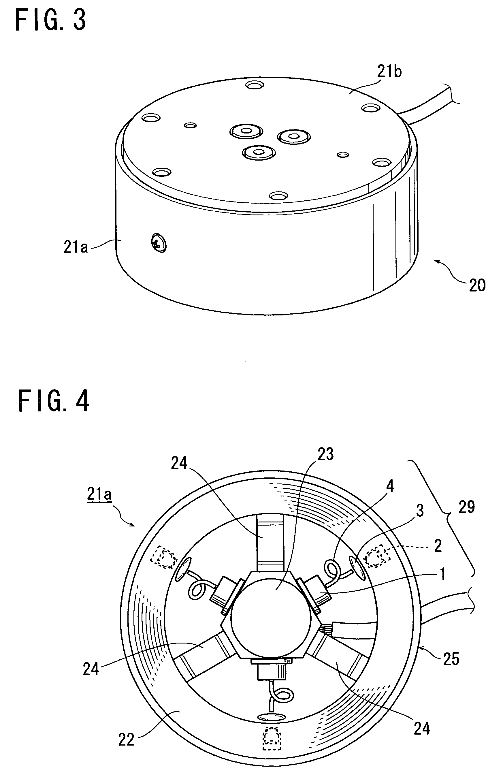
[0031]One embodiment of the present invention will hereinafter be described with reference FIGS. 3 to 7. Referring first to FIG. 3, a six-axis force sensor 20 is structurally composed of a cylindrical main body 21a, a disk-like top lid 21b, and a disk-like bottom lid (not seen). Referring now to FIG. 4, the main body 21a is constituted basically by a frame 25, which integrally includes: a cylindrical support section 22; an action section 23 disposed centrally inside the support section 22 and adapted to receive an external force; and three elastic spoke sections 24 crookedly structured so as to readily provide elastic deformation in all directions and supportably connecting the action section 23 to the support section 22. The frame 25 is made of a single piece of an aluminum alloy material and shaped by cutting and electric discharge machining. The support section 22 and the action section 23 are fixed respectively to two components to which a measurement force is applied, and when...

second embodiment

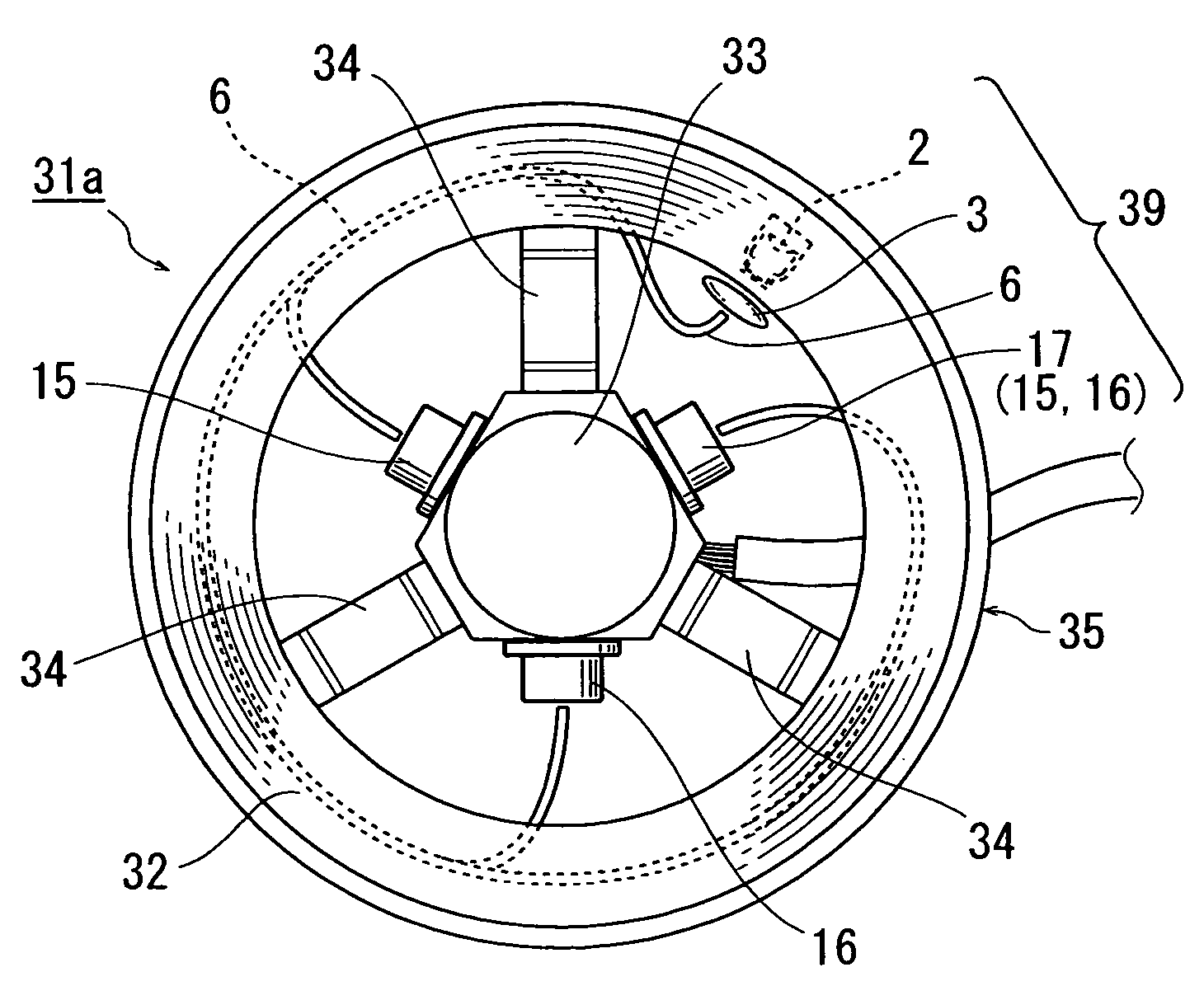
[0038]Another embodiment of the present invention will be described with reference to FIGS. 8 to 10. Referring first to FIG. 8, a six-axis force sensor 30 is structurally composed of a cylindrical main body 31a, a disk-like top lid 31b, and a disk-like bottom lid (not seen). Referring now to FIG. 9, the main body 31a is constituted basically by a frame 35, which integrally includes: a cylindrical support section 32; an action section 33 disposed centrally inside the support section 32 and adapted to receive an external force; and three elastic spoke sections 34 crookedly structured so as to readily provide elastic deformation in all directions and supportably connecting the action section 33 to the support section 32. The frame 35 is made of a single piece of an aluminum alloy material and shaped by cutting and electric discharge machining. The support section 32 and the action section 33 are fixed respectively to two components to which a measurement force is applied, and when the...


PUM

PropertyMeasurementUnit
diameteraaaaaaaaaa
diffusing angleaaaaaaaaaa

Abstract

An optical displacement sensor is provided, in which an optical fiber is disposed between a light source and a light receiving means so that light emitted from the light source is conducted therethrough so as to be duly received by the light receiving means whereby a beam diameter can be controlled and a uniform intensity distribution of emitted light can be ensured without providing a pinhole aperture. Also, a six-axis force sensor incorporating such an optical displacement sensor is provided.

Description

BACKGROUND OF THE INVENTION[0001]1. Field of the Invention[0002]The present invention relates to an optical displacement sensor and an external force detecting device, and particularly to an optical displacement sensor which detects relative displacement between a reference object and a measurement object based on displacement of a light reception position, and further to an external force detecting device which detects an external force applied to the measurement object based on a signal outputted from the optical displacement sensor.[0003]2. Description of the Related Art[0004]An external force detecting device, such as a six-axis optical force sensor, is conventionally known, in which a displacement amount of an action section to receive an external force, namely a measurement object, relative to a support section to support the action section, namely a reference object, is detected by an optical displacement sensor, and the external force received at the action section is measur...

Claims


Application Information

Patent Timeline
Patent Type & Authority Patents(United States)
IPC IPC(8): G01N21/86G01B11/02G01B9/02G01D5/34G01J1/04G01L5/16G01B11/00G01D5/26G01D5/347
CPCG01D5/268G01D5/34723
Inventor KITAMURA, ATSUSHIADACHI, SHIGEYUKI
Owner MINEBEA CO LTD
Why Eureka
Try Eureka