Method of forming holographic grating

a technology of holographic grating and manufacturing method, which is applied in the direction of optical radiation measurement, instruments, spectrometry/spectrophotometry/monochromators, etc., can solve the problems of poor production efficiency, high selection ratio, and high etching speed, and achieves low cost and high performance. , the effect of dramatically improving the durability

Inactive Publication Date: 2006-10-31
SHIMADZU CORP
View PDF12 Cites 23 Cited by
  • Summary
  • Abstract
  • Description
  • Claims
  • Application Information

AI Technical Summary

Benefits of technology

[0015]In the present invention, by mixing oxygen with the fluorine based etching gas, carbon deposited on the front surface of the photoresist is reacted with oxygen to form carbon dioxide, so that carbon is removed from the front surface of the resist to obviate the carbon rich condition. Thus, the front surface of the grating can be prevented from being clouded. Also, there is no incident that the front surface of the resist has the Teflon structure to prevent the etching.
[0016]Further, since the etching is carried out until all of the resist layer is deleted and the optical glass base plate itself is directly engraved, there is solved the conventional problem that the damage tends to occur at the parting step in case of forming a replica, resulting in improving the durability dramatically. As a result, as compared to the conventional method, in which only ten sheets of the replica can be approximately formed from one sheet of the

Problems solved by technology

In the generally used reactive ion beam etching (RIBE) method, a selection ratio=(etching speed with respect to a base plate)/(etching speed with respect to a resist layer), which is defined according to a kind of the etching gas and materials of the base plate or the resist, becomes an issue in many

Method used


Image

  • Method of forming holographic grating
  • Method of forming holographic grating
  • Method of forming holographic grating

Examples


Embodiment Construction

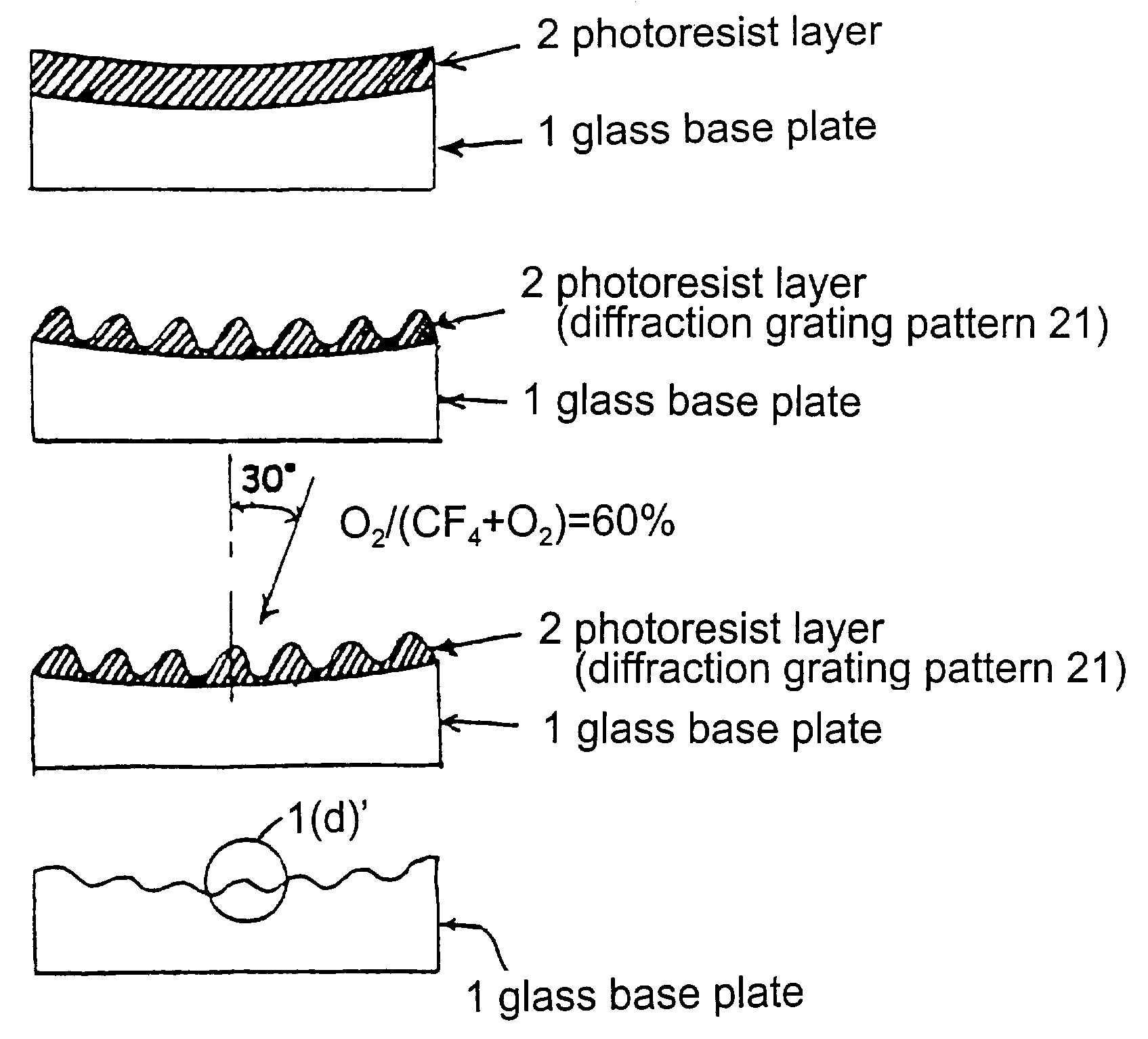
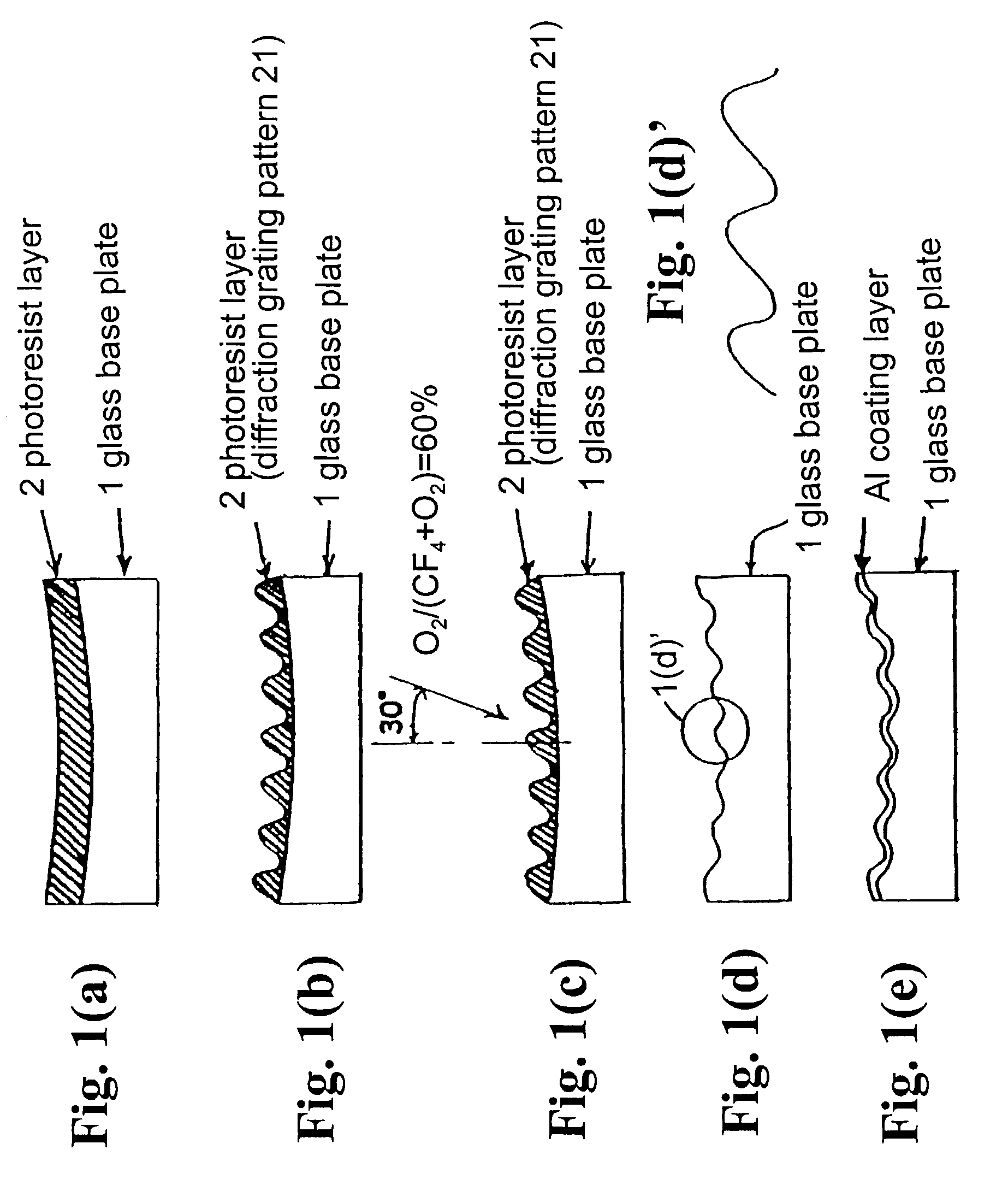
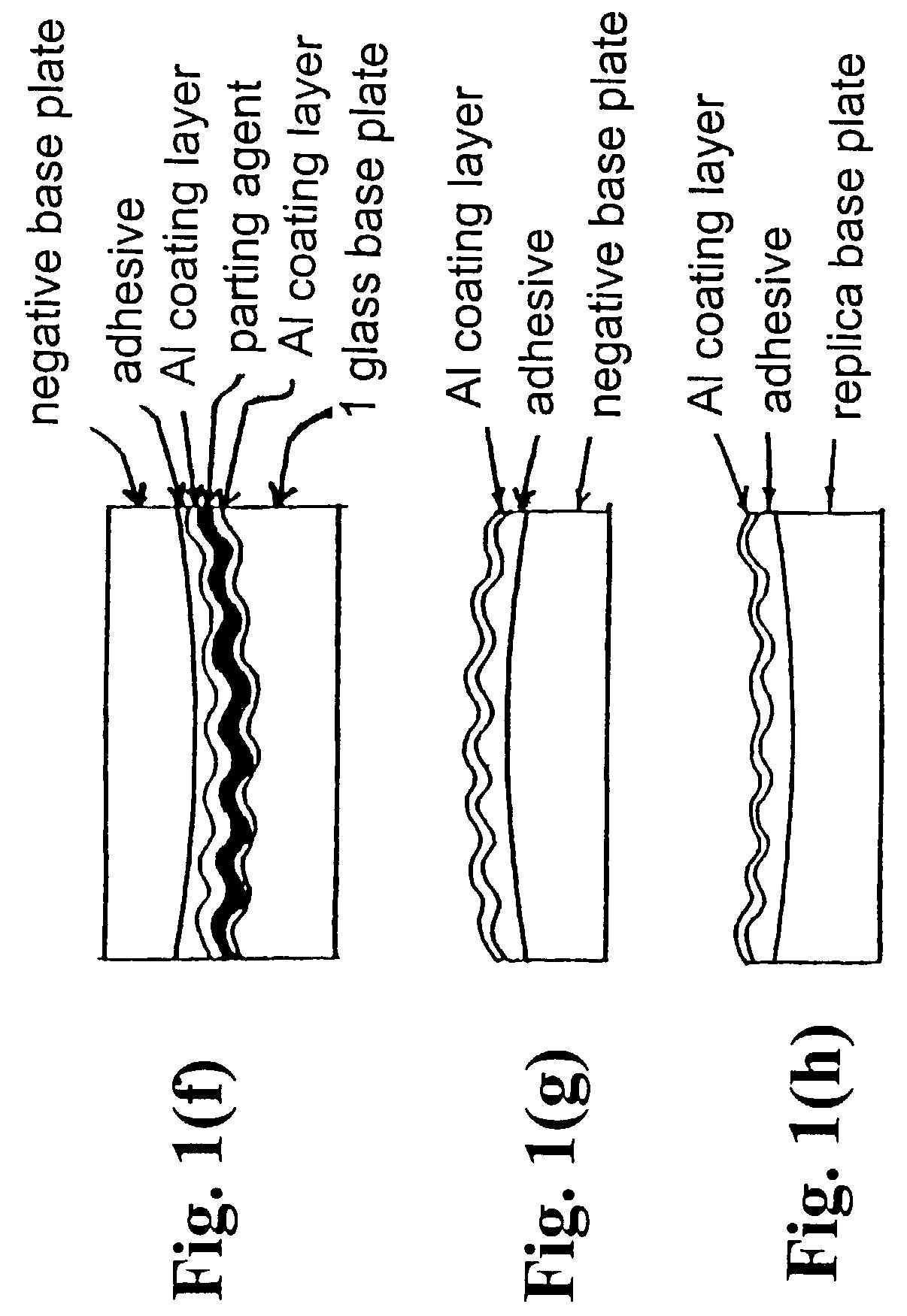
[0020]Hereunder, an embodiment of a method for forming a holographic grating according to the present invention will be explained with reference to the attached drawings.

[0021]In FIG. 1(a), numeral 1 designates a base plate or substrate made of optical glass. The base plate is a blank for an original of a diffraction grating, and can be any kind as long as the base plate can be optically polished and the resist can be coated thereon. However, the optical glass is low in coefficient of expansion by a thermal change, and is excellent as a material for the base plate of the diffraction grating which is an optical element. For example, a low-expansion crystal glass, such as BK7, BSC2, Pyrex glass, soda glass, quartz glass, “ZERODUR” (manufactured by Scott Glasswerke), or “CRYSTORON” (manufactured by HOYA CORPORATION), can be used satisfactorily, and in the invention, BK7 glass is used as an example in the present embodiment. Firstly, the BK7 glass (approximately 60 mm×60 mm×11.3 mm) is ...


PUM


Abstract

In a method of forming a holographic grating, a photoresist layer is formed on an optical substrate, and a resist pattern is formed in the photoresist layer to have grooves depth deeper than a predetermined depth of diffraction grating grooves to be formed. Then, the photoresist layer with the resist pattern is etched by an ion beam generated by a mixed gas containing a fluorine based gas and oxygen until the resist pattern is substantially completely disappears. Thus, the diffraction grating grooves having the predetermined depth are directly engraved on the optical glass plate.

Description

CROSS-REFERENCE TO RELATED APPLICATION[0001]This is a divisional application of Ser. No. 09 / 735,556, filed on Dec. 14, 2000, now abandoned.BACKGROUND OF THE INVENTION AND RELATED ART STATEMENT[0002]The present invention relates to a method of manufacturing a grating or diffraction grating as a wavelength separating / selecting element used in a spectroscope or a branching filter, and particularly, the present invention relates to a method of manufacturing a holographic grating by a holographic exposure method.[0003]A grating or diffraction grating is a wavelength separating / selecting element used in a spectroscope, a branching filter, or the like. In generally classifying the forming methods thereof, there have been known a mechanical method, wherein grating grooves are mechanically engraved by a ruling engine; and a holographic exposure method, wherein interference fringes by interference of two beams are exposed and developed in a photoresist layer coated on a base plate, so that a ...

Claims


Application Information

Patent Timeline
IPC IPC(8): G03C5/00B29D11/00G02B5/18C03C15/00G01J3/18G02B5/32G03F7/00G03F7/36G03F7/40G03H1/04
CPCG01J3/1838G03F7/0005G03H1/028G03H2260/63G03H1/0244G03H2001/0296
Inventor KOEDA, MASARUTANAKA, YUJISOEJIMA, AKIO
Owner SHIMADZU CORP
Why Eureka
Try Eureka