Feed forward equalizer controlled by FEC correction rates

a technology of correction rate and equalizer, applied in the field of signal equalization, can solve the problems of increasing the power consumption of the output interface, performance degradation of the parallel comparator structure,

Inactive Publication Date: 2006-10-31
LUCENT TECH INC
View PDF3 Cites 13 Cited by
  • Summary
  • Abstract
  • Description
  • Claims
  • Application Information

AI Technical Summary

Benefits of technology

[0025]It is advantageous to increase the parameter to be multiplied with the signal having the smallest delay among the three signals if the fourth conditional error is smaller than the third conditional error and decrease the parameter if the fourth conditional error is larger than the third conditi

Problems solved by technology

The major problem for the generation of a control signal is the realization of a high speed sample and hold circuit to sample the analog signal or the implementation of an “eye monitor”, which may be understood as additional threshold with an exclusive-or-function of the current threshold.
Those parallel comparator

Method used


Image

  • Feed forward equalizer controlled by FEC correction rates
  • Feed forward equalizer controlled by FEC correction rates
  • Feed forward equalizer controlled by FEC correction rates

Examples


Embodiment Construction

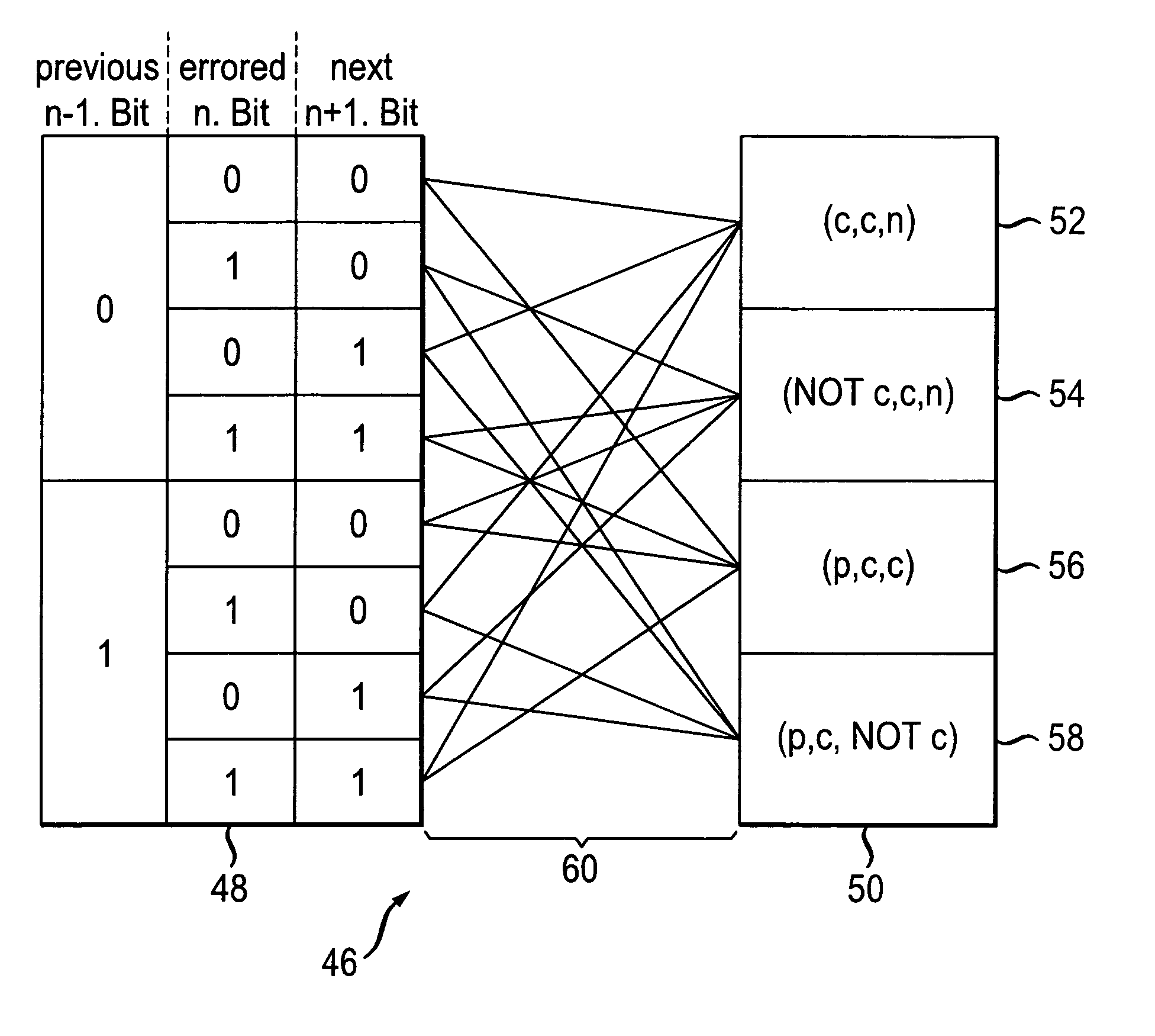
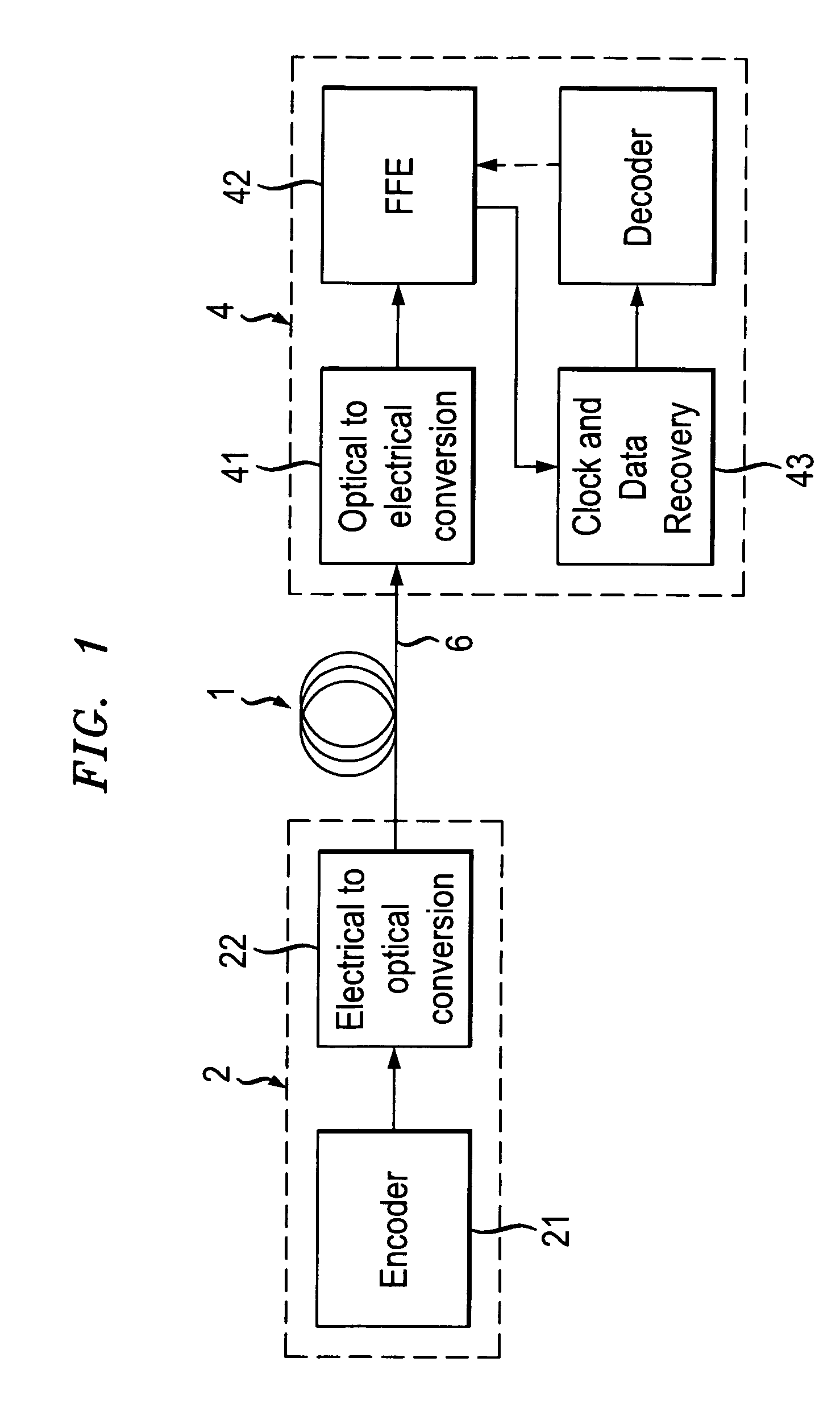
[0035]Reference is now made to FIG. 1 showing components of an optical transmission channel 1. The channel comprises a transmitter 2, which includes an encoder 21 to encode the data stream for FEC and an electrical to optical converter 22 to convert the electrical signals for optical transmission. The encoded and converted data stream is transmitted via an optical fiber. A receiver 4 retrieves the data from the received optical signals. In order to retrieve the data, the received optical signals are converted back to electrical signals by means of a converter 41. It is further necessary to retrieve the clock and sampling phase from received signal, which is generally carried out by means of a clock and data recovery circuit 43. Data are recovered in a decoder, wherein the converted analogue signal is digitised to a bit stream by means of a signal threshold or decision threshold and the recovered clock and sample phase. Finally, a decoding scheme is applied to the bit stream to retri...


PUM


Abstract

A method of signal equalization of a transmitted bit stream by means of a feed forward equalizer is provided, whereby the signal is decomposed into at least two components and the components are multiplied with equalization parameters to form equalized components, which are superposed to form an equalized signal, and whereby conditional bit error rates by counting faulty transmitted bits in dependence of preceding and succeeding bits are determined and the equalization parameters are tuned dependent on the determined conditional bit error rates.

Description

CROSS REFERENCE TO RELATED APPLICATION[0001]This application claims priority of European Application No. 01308632.7 filed on Oct. 9, 2001.FIELD OF THE INVENTION[0002]The invention relates to a method for signal equalization in a signal receiving unit comprising a feed forward equalizer, in particular to the adjustment of equalization parameters used to equalize the received signals and to a feed forward equalizer adapted to carrying out the adjusting method.BACKGROUND OF THE INVENTION[0003]In long distance transmission systems at high bit rates over optical fibers, signal distorting effects occur which reduce the eye opening at the receiver. The distortion may be due to linear or non-linear effects, such as group velocity dispersion (GVD), polarization mode dispersion (PMD), transmitter chirp, extinction ratio, or intersymbol interference (ISI) induced by non-linearities of the fiber. These effects reduce the eye opening at the receiver and thereby lead to a reduced tolerable optica...

Claims


Application Information

Patent Timeline
IPC IPC(8): H03H7/30H03H7/40H03K5/159H04L25/03
CPCH04L25/03038H04L2025/03477H04L2025/03617
Inventor HAUNSTEIN, HERBERTSCHLENK, RALPHSTICHT, KONRAD
Owner LUCENT TECH INC
Why Eureka
Try Eureka