
Active filter

a filter and active technology, applied in the field of active filters, can solve the problems of difficult control, undesirable capacitance ratio, difficult control, etc., and achieve the effects of reducing the combined capacitance of the capacitive elements, and reducing the capacitance of the feedback section

Inactive Publication Date: 2006-11-07
SHARP KK
View PDF6 Cites 11 Cited by
  • Summary
  • Abstract
  • Description
  • Claims
  • Application Information

AI Technical Summary

Benefits of technology

The present disclosure addresses the problem of reducing the capacitance of the feedback section of an operational amplifier in a semiconductor integrated circuit device. The solution involves connecting multiple capacitive elements between the output terminal and the inverting or non-inverting input terminals. This reduces the combined capacitance of the elements and prevents deterioration of signal-to-noise ratio, increased switching noise, and power dissipation, while also reducing the capacitance ratio. This approach can be easily integrated into existing processes.

Problems solved by technology

However, it is difficult to control the very small capacitance of such a capacitor.
Thus, a large capacitance ratio is undesirable.
For example, if it is assumed that the maximum capacitance of a capacitor for use in the eighth-order filter is limited to 5 pF (C1), then a capacitance C2 satisfies C2=5 pF / 59.1(≈0.084 pF), which is on the order of the layout parasitic capacitance, and therefore difficult to control.
This technique, however, is not adequate because the reduction of the input signal degrades the Signal-to-Noise ratio.
The main drawbacks of this technique are: (i) the high-value resistor introduces thermal noise into the capacitor, and (ii) the clocking of the capacitors requires a sampling frequency much higher than the cut-off frequency of the filter.
This causes an increase in switching noise and power dissipation.
The state-of-the-art implementations of high-order active R-C filters suffer from the need of high ratio of capacitances.
This causes deterioration of the signal-to-noise ratio (SNR), when the prior art techniques are used in wireless transceivers.
This causes an increase in switching noise and power dissipation.

Method used


Image

  • Active filter
  • Active filter
  • Active filter

Examples


Embodiment Construction

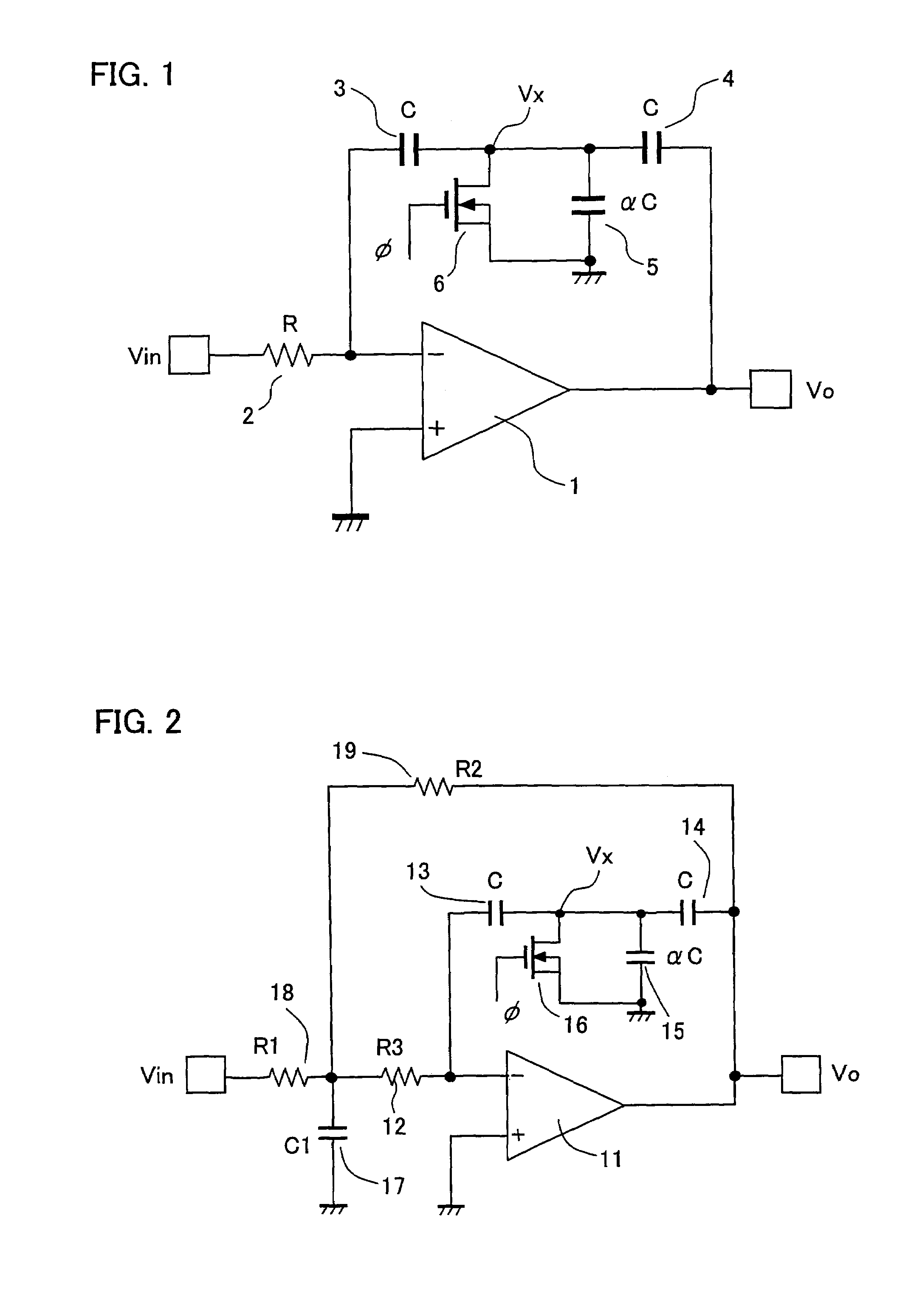
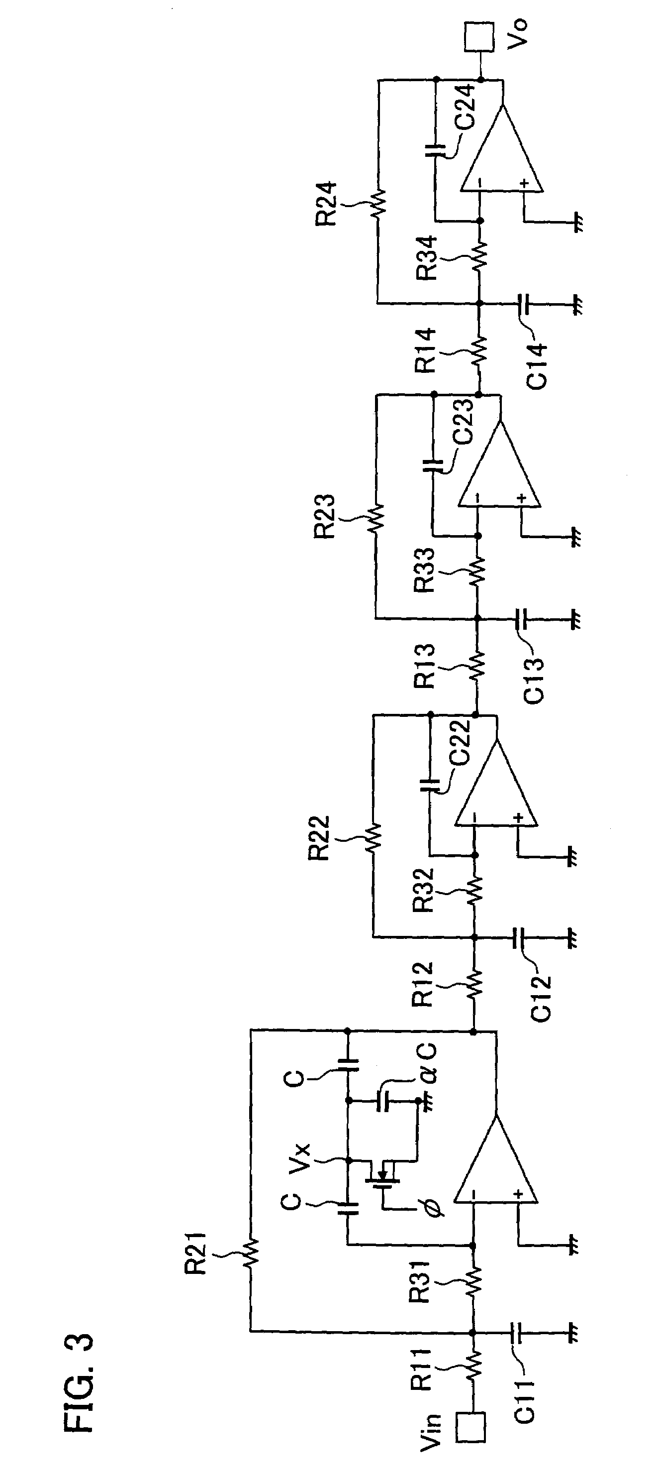
[0042]The following description deals with one embodiment of the present disclosure with reference to FIG. 1 through FIG. 3.

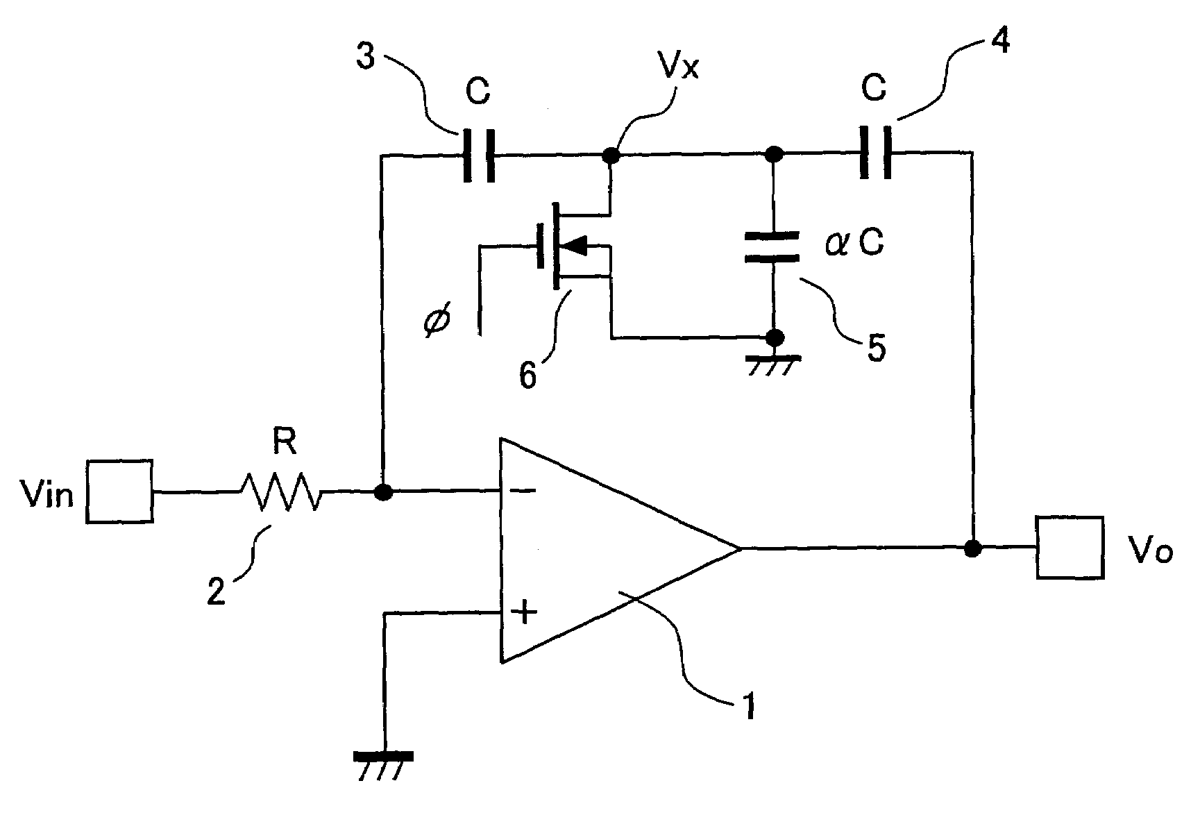
[0043]FIG. 1 illustrates an integrator circuit to which a main concept of an active filter of the present disclosure is applied. As shown in FIG. 1, the integrator circuit includes an operational amplifier 1, a resistor 2, a plurality of capacitors 3 through 5, an input terminal to which an analog input signal Vin is supplied, and an output terminal from which an output signal Vo is outputted.

[0044]In the integrator circuit, the resistor 2 (having resistance R) is provided between (i) an input terminal to which the analog input signal Vin is supplied and (ii) an inverting input terminal of the operational amplifier 1. The capacitors 3 through 5 are connected to one another so as to have a Tconnection between the inverting input terminal and the output terminal of the operational amplifier 1.

[0045]The resistor 2 and the capacitors 3 through 5 of the operational ...


PUM


Abstract

In order to reduce capacitance of a feedback section of an operational amplifier provided in a semiconductor integrated device, an active filter includes an operational amplifier in which a plurality of capacitive elements are connected between (i) an output terminal and (ii) an inverting input terminal or an input terminal. This arrangement does not require any special technique and amendment of an ordinary integrated circuit process. Further, this arrangement ensures small capacitance in the feedback section of the operational amplifier, while preventing deterioration in S / N ratio, and increases in switching noise and power consumption.

Description

CROSS-REFERENCE TO RELATED APPLICATION[0001]This Nonprovisional application claims priority under 35 U.S.C. § 119(a) on Patent Application No. 2004 / 018532 filed in Japan on Jan. 27, 2004, the entire contents of which are hereby incorporated by reference.FIELD OF THE DISCLOSURE[0002]The present disclosure technology relates to an active filter that can reduce capacitance of a feedback section of an operational amplifier provided in a semiconductor integrated circuit device.BACKGROUND OF THE DISCLOSURE[0003]An analog frequency filter is a common building block in communication, audio, signal processing, and the like. An analog active filter is realized, in a semiconductor integrated circuit, by an operational amplifier, a resistor(s), a capacitor(s), and an inductor(s). The operational amplifier serves as an active element, whereas the resistor(s), the capacitor(s), and the inductor serve as passive components.[0004]In general, integration of inductors in a semiconductor occupies a la...

Claims


Application Information

Patent Timeline
Patent Type & Authority Patents(United States)
IPC IPC(8): H03K5/00H03H11/04H03B1/00H03H7/01H03H11/12H03H19/00
CPCH03H11/1278H03H11/1217
Inventor ADAN, ALBERTO OSCAR
Owner SHARP KK
Learn More