Transcutaneous medical device dressings and method of use

a technology of medical devices and dressings, applied in the field of transcutaneous medical device dressings, can solve the problems of increasing hospital costs, high risk of infection from transcutaneous infection, and more cases of death,

Inactive Publication Date: 2006-11-21
NUCRYST PHARMA
View PDF155 Cites 121 Cited by
  • Summary
  • Abstract
  • Description
  • Claims
  • Application Information

AI Technical Summary

Benefits of technology

[0036]“Partly reflective” when used to describe the base or top layer materials, means that the material has a surface which reflects a portion of incident light, but which also transmits a portion of the incident light. Reflection occurs when a ray of incoming light encounters a boundary or interface charac

Problems solved by technology

All of these transcutaneous medical devices, when in place, have a portion of the device which is external, that is which is left protruding from the skin, and which can be the cause of infection.
The risk of acquiring infections from transcutaneous infections is very high.
This nosocomial bloodstream infections cause a case fatality of more than 20%, and account for an increase of thousands of dollars in hospital costs per infection, or tens of thousands of dollars per survivor in ICU needing an extra week of hospital stay.
A further topical ointment after insertion of the device, such as an ointment containing neomycin, polymyxin and bactracin, has been shown to prevent catheter colonization/infection, but it may increase the risk of fungal infection.
Ointments are also inconvenient, requiring multiple replacements.
However, none of these efforts has been completely successful in clinical trials.
Presently, the most common catheter dressing used in hospi

Method used


Image

  • Transcutaneous medical device dressings and method of use
  • Transcutaneous medical device dressings and method of use
  • Transcutaneous medical device dressings and method of use

Examples


example 1

[0094]This example shows the preparation of a bilayer anti-microbial silver coating on a dressing material. A high density polyethylene dressing, DELNET™ or CONFORMANT 2™ was coated with a silver base layer and a silver / oxide top layer to generate a coloured anti-microbial coating having indicator value. The coating layers were formed by magnetron sputtering under the conditions set out in Table 1.

[0095]

TABLE 1Sputtering Conditions:Base LayerTop LayerTarget99.99% Ag99.99% AgTarget Size20.3 cm diameter20.3 cm diameterWorking Gas96 / 4 wt % Ar / O296 / 4 wt % Ar / O2Working Gas Pressure40 mTorr40 mTorrPower0.3 kW0.15 kWSubstrate Temperature20° C.20° C.Base Pressure3.0 × 10−6 Torr3.0 × 10−6 TorrAnode / Cathode Distance100 mm100 mmSputtering Time7.5–9 min1.5 minVoltage369–373 V346 V

[0096]The resulting coating was blue in appearance. A fingertip touch was sufficient to cause a colour change to yellow. The base layer was about 900 nm thick, while the top layer was 100 nm thick.

[0097]A zone of inhib...

example 2

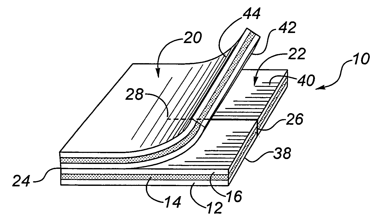
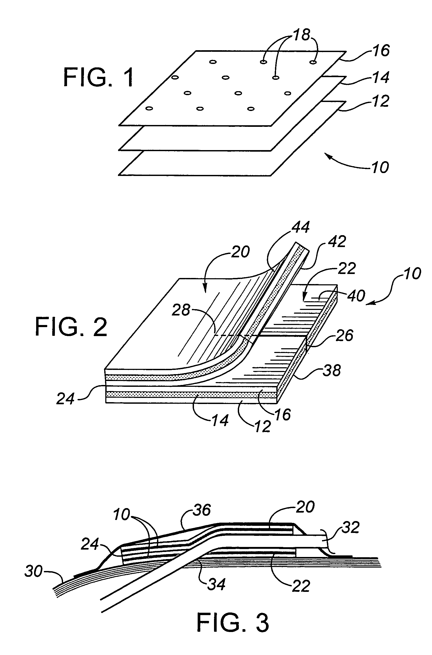
[0100]This example is included to demonstrate a multilayer transcutaneous device dressing in accordance with the present invention. High density polyethylene mesh dressing material DELNET™ or CONFORMANT 2™ dressing was coated with a bilayer blue anti-microbial coating as set forth in Example 1. using the sputtering conditions of Table 1. Two layers of this coated dressing material were placed above and below an absorbent core material formed from needle punched rayon / polyester (SONTARA™ 8411). With the silver coating on both the first and third layers, the dressing may be used with either the blue coating side or the silver side in the skin facing position. For indicator value, it might be preferable to have the blue coating visible. The three layers were laminated together by ultasonic welding to produce welds between all three layers spaced at about 2.5 cm intervals across the dressing. This allowed the dressing to be cut down to about 2.5 cm size portions for smaller dressing nee...

example 3

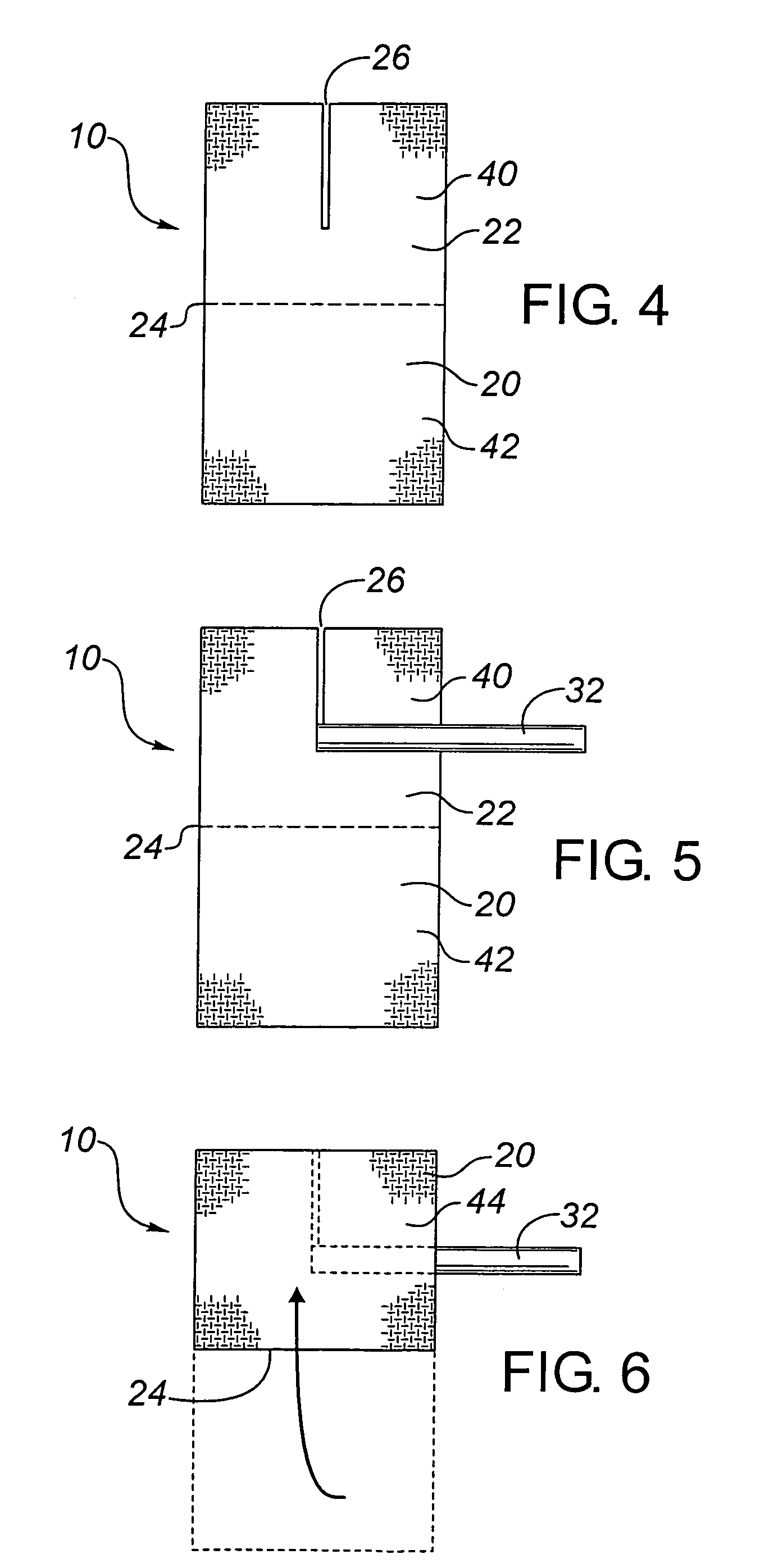
[0102]This animal study evaluated four prototype catheter dressings, one of which was in made in accordance with Example 2 above, the others being 3 cm disc shaped catheter dressings of laminated dressing materials, having a thickness less than about 1 mm, formed with a slit to their center to fit beneath the catheter, and being coated with a silver coating deposited as in Example 1. The silver coatings were prepared in a full scale roll coater under conditions to provide coatings having the same properties set out in Examples 2 and 3 above.

[0103]The prototype dressings were as follows:[0104]1. Silver Catheter Dressing, prepared as in Example 2, with a top and a bottom dressing sized 5.1×5.1 cm, with a 2.6 cm slit in the bottom dressing, as an example of this invention.[0105]2. Silver Disc 1—A 3 cm disc of the dressing material of Example 2, but used only as a flat disc beneath the catheter (i.e., with no top dressing)[0106]3. Silver Disc 2—A 3 cm disc of the dressing material which...


PUM


Abstract

A transcutaneous device dressing and method for its use with a transcutaneous medical device, such as an intravascular catheter, which punctures the skin of a patient and which has a portion of the medical device protruding from the skin which can lead to infection. The dressing includes a top and a bottom dressing, both being formed from a flexible material and having upper and lower surfaces, with the lower surface being the skin facing surface in use. The bottom dressing has a slit formed therein extending from one edge inwardly to a termination point within the confines of the bottom dressing. An anti-microbial material is provided without the use of adhesives at the upper and lower surfaces of the bottom dressing, and at least at the lower surface of the top dressing. In use, the bottom dressing is placed next to the skin, the slit allowing the bottom dressing to surround the puncture site such that the lower surface of the bottom dressing is in contact with the skin while the upper surface of the bottom dressing is in contact with a portion of the medical device protruding from the skin. The top dressing is placed above the puncture site such that its lower surface is in contact with a portion of the medical device protruding from the skin. In this way, there is exposure of the portion of the medical device protruding from the skin to the anti-microbial activity of the anti-microbial material.

Description

FIELD OF THE INVENTION[0001]The invention relates to transcutaneous medical device dressings, and processes for their production and use, for controlling infections.BACKGROUND OF THE INVENTION[0002]Transcutaneous medical devices are catheters, pins, implants and the like which pass through the skin and are indwelling for some considerable time. Exemplary of transcutaneous medical devices are central venous catheters, peripheral venous catheters, Swan-Gaus pulmonary catheters, central nervous system implants (ex. external ventricular drainage and ventricular reservoirs), peritoneal dialysis catheters, such as for continuous ambulatory peritoneal dialysis and continuous cyclic peritoneal dialysis, hemodialysis catheters, transvenous pacemaker leads and temporary orthopedic pins. All of these transcutaneous medical devices, when in place, have a portion of the device which is external, that is which is left protruding from the skin, and which can be the cause of infection.[0003]The ris...

Claims


Application Information

Patent Timeline
IPC IPC(8): A61M5/32A61F13/00A61L2/16A61M25/02
CPCA61M25/02A61M2025/026A61M2025/0266A61M2025/0253A61M2025/0273
Inventor BURRELL, ROBERT EDWARDYIN, HUA QING
Owner NUCRYST PHARMA
Why Eureka
Try Eureka