Current sensor using mirror MOSFET and PWM inverter incorporating the same

a current sensor and mirror mosfet technology, applied in the direction of electric variable regulation, process and machine control, instruments, etc., can solve the problems of thermal breakdown, increase the cost of current sensor and the size of pwm inverter, and the inability of the method to detect both a current in the positive direction and a current in the negative direction, and achieve the effect of small and inexpensive pwm inverter

Inactive Publication Date: 2006-11-21
HITACHI ASTEMO LTD
View PDF29 Cites 19 Cited by
  • Summary
  • Abstract
  • Description
  • Claims
  • Application Information

AI Technical Summary

Benefits of technology

[0008]An object of the present invention is to provide a current sensor that does not require a separate device or circuit for current detection and can detect currents both in the positive and negative directions, and also to provide a small and inexpensive PWM inverter that uses said current sensor.

Problems solved by technology

If a current flows for a long time or an overcurrent occurs, the power MOSFET itself generates heat causing a thermal breakdown to occur.
However, a current detection means that uses an insulated current sensor or uses both a shunt resistor and a sample-and-hold circuit requires a separate device or circuit, resulting in increasing both the current sensor cost and the size of the PWM inverter, which is a problem.
However, there is a problem that the current detection method described in the Japanese Applicatio n Patent Laid-open Publication No. 2000-193692 cannot be applied to the current detection of the PWM inverter because it is impossible for the method to detect both a current in the positive direction and a current in the negative direction.
Therefore, it is difficult to detect a reverse current, that is, a forward current flowing through a parasitic diode of the power MOSFET.
It is difficult for the comparator to detect both of those voltage signals, and therefore, there is a problem that the method cannot be applied to the current detection of the PWM inverter.
As a result, in this area, it is not possible to accurately detect current that flows through the power MOSFET.

Method used


Image

  • Current sensor using mirror MOSFET and PWM inverter incorporating the same
  • Current sensor using mirror MOSFET and PWM inverter incorporating the same
  • Current sensor using mirror MOSFET and PWM inverter incorporating the same

Examples


second embodiment

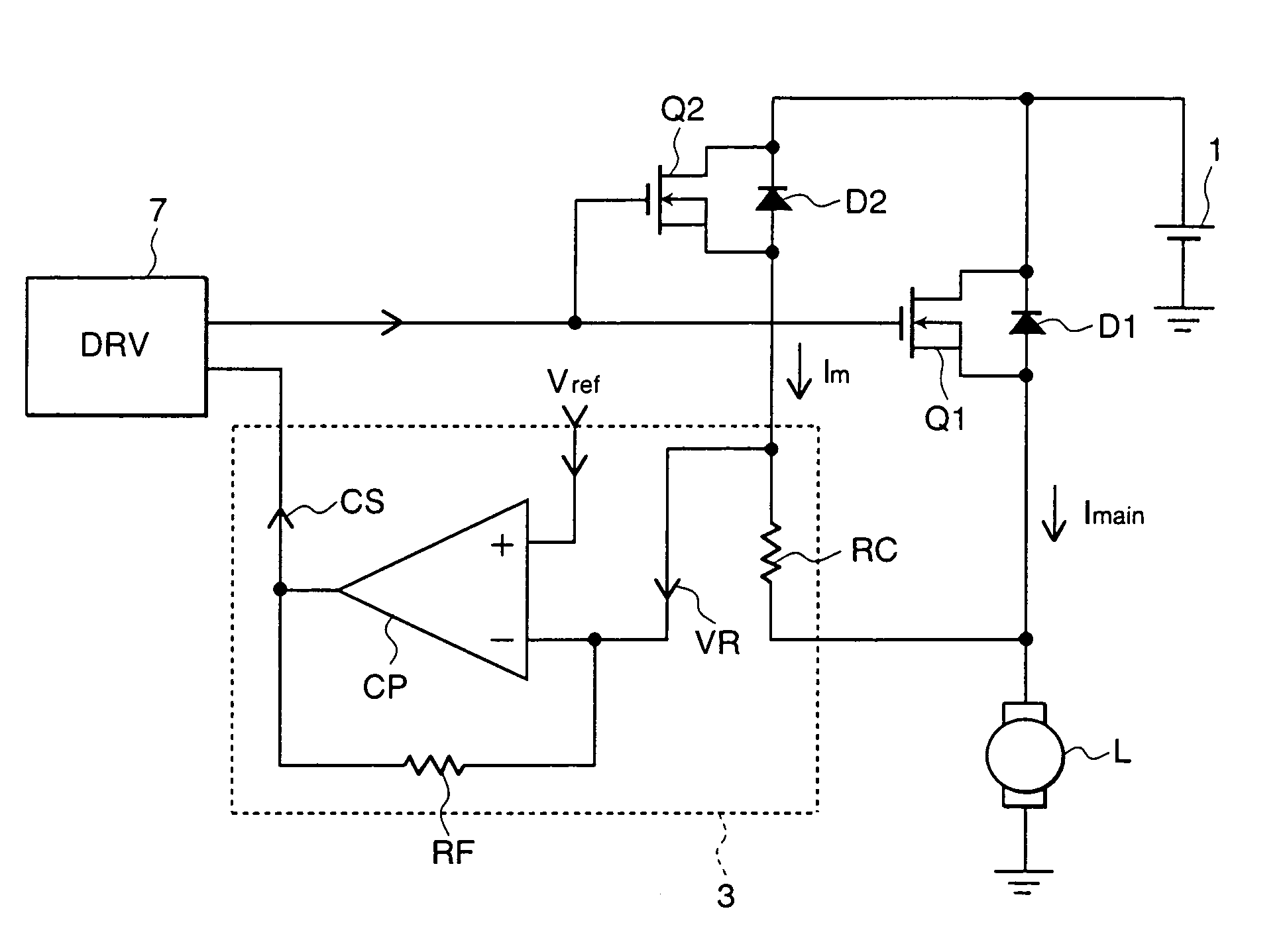
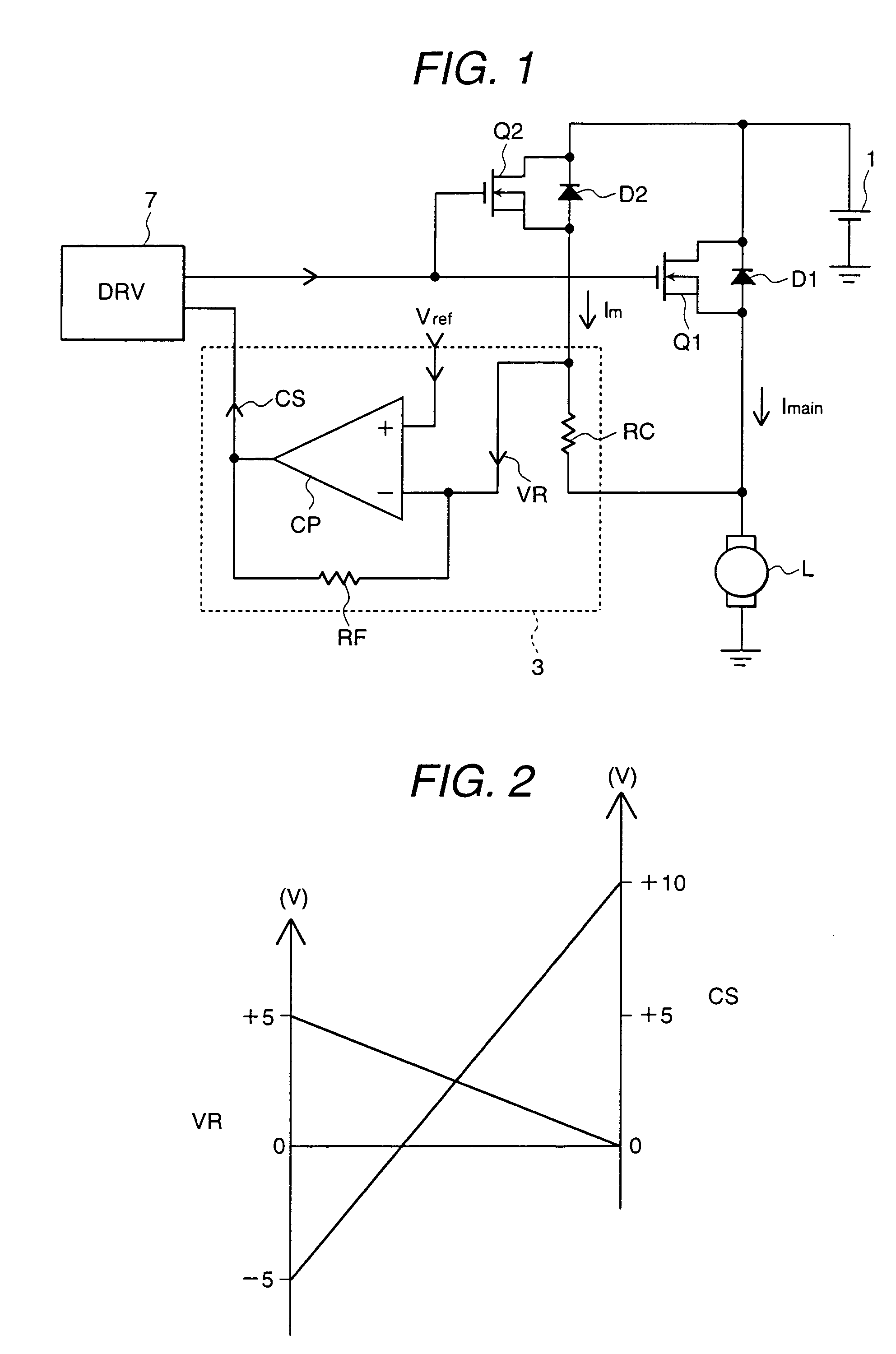
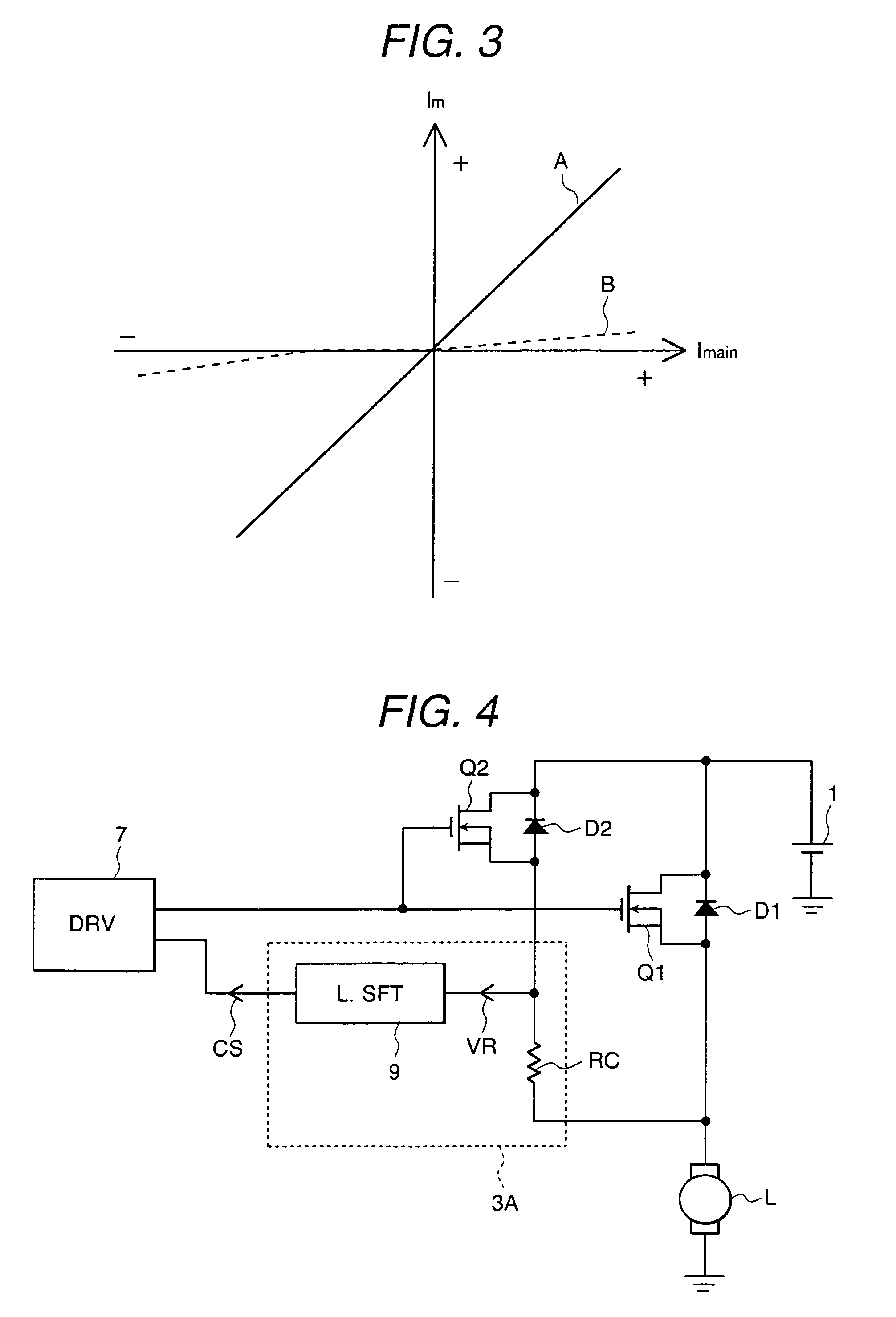
[0064]Next, with reference to FIGS. 4 and 5, the configuration of a current sensor according to the present invention will be described.

[0065]FIG. 4 is a circuit diagram that shows the configuration of a current sensor according to a second embodiment of the present invention. FIG. 5 is an explanatory diagram that explains characteristics of the level shift circuit used for a current sensor according to a second embodiment of the present invention. Moreover, items in FIGS. 4 and 5 are identical to those in FIG. 1 when the same alphanumeric characters appear.

[0066]As shown in FIG. 4, in this embodiment, a current detection circuit 3A consists of a level shift circuit 9 and a current detection resistor RC. Herein, the resistance value of the current detection resistor RC is specified in the same manner as the current sensor 3 shown in FIG. 1.

[0067]As FIG. 5 shows, when voltage signal VR of the current detection resistor RC changes, for example, from −5 V to +5 V, the level shift circu...

third embodiment

[0069]Next, with reference to FIG. 6, the configuration of a current sensor according to the pr esent invention will be described.

[0070]FIG. 6 is a circuit diagram that shows the configuration of a current sensor according to a third embodiment of the present invention. Items in FIG. 6 are identical to those in FIG. 1 when the same alphanumeric characters appear.

[0071]In this embodiment, a current sensor 3B consists of only a current detection resistor RC. Herein, the resistance value of the current detection resistor RC is specified in the same manner as the current sensor 3 shown in FIG. 1. Voltage signal VR of the current detection resistor RC is directly inputted into the driving device 7A.

[0072]On the other hand, the driving device 7A is driven by a positive power supply VB+ and a negative power supply VB−. This enables the driving device 7 to capture both positive and negative voltage signals VR, thereby accurately detecting currents that flow through the power MOSFET Q1 in bo...

first embodiment

[0074]Next, with reference to FIGS. 7 through 9, the configuration of a PWM inverter that uses a current sensor according to the present invention will be described. Herein, a PWM inverter controls three-phase alternating current by using a current sensor.

[0075]FIG. 7 is a circuit diagram that shows the configuration of the PWM inverter that uses a current sensor according to a first embodiment of the present invention. Items in FIG. 7 are identical to those in FIG. 1 when the same alphanumeric characters appear.

[0076]In FIG. 7, a PWM inverter consists of an inverter main circuit 2, current sensors 3U, 3V and 3W, a driving device 7 and an electrolytic capacitor 8. The PWM inverter converts a direct current output voltage of the DC power source 1 into a three-phase alternating current and supplies the three-phase output current to an AC motor 6, a load. Moreover, the electrolytic capacitor 8 is connected in parallel to the DC power source 1.

[0077]The inverter main circuit 2 consists ...


PUM


Abstract

A current sensor has a power MOSFET Q1, connected between an electric load and a power supply, for controlling current that flows through said electric load, a mirror MOSFET Q2, connected in parallel to said power MOSFET Q1, in which a portion of the current flowing through said power MOSFET flows, and a current detection resistor RC connected between a source electrode of said power MOSFET and a source electrode of said mirror MOSFET. An inverting amplifier circuit CP of the current sensor 3 inverts and amplifies the voltage signal, which has been converted to voltage by the current detection resistor RC, and outputs the signal, thereby converting positive and negative voltages generated across the current detection resistor RC to a positive voltage.

Description

BACKGROUND OF THE INVENTION[0001]The present invention relates to a current sensor and a PWM (Pulse Width Modulation) inverter that uses the current sensor, and particularly relates to a current sensor which is suitable for detecting currents flowing in both the positive and negative directions and a PWM inverter which incorporates said current sensor.[0002]Conventionally in automobiles, a power MOSFET (Metal Oxide Semiconductor Field Effect Transistor), which is a switching element for controlling electrical components of the automobile, is used to control current flowing through electrical components. If a current flows for a long time or an overcurrent occurs, the power MOSFET itself generates heat causing a thermal breakdown to occur. Furthermore, in a PWM inverter that uses a power MOSFET for controlling three-phase alternating current, current flows through the power MOSFET in two directions: from a drain electrode of the power MOSFET to a source electrode, and the reverse dir...

Claims


Application Information

Patent Timeline
Patent Type & Authority Patents(United States)
IPC IPC(8): H02P7/29G05F1/56G01R19/00H02M7/537H02M7/5387
CPCH02M7/537H02M7/53871H02M2001/0009H02M1/0009
Inventor FUJINO, SHINICHISAKANO, JUNICHIINNAMI, TOSHIYUKIGOTO, KOHSEI
Owner HITACHI ASTEMO LTD
Why Eureka
Try Eureka