
Multilayer microporous membrane

a microporous membrane and microporous membrane technology, applied in the field of multi-layer microporous membranes, can solve the problems of inability to remove viruses with a smaller pore diameter, inability to achieve virus removal, and inability to achieve thermally stable viruses. achieve superior permeability, superior permeability, and performance sufficient

Inactive Publication Date: 2006-11-28
ASAHI KASEI MEDICAL CO LTD
View PDF46 Cites 22 Cited by
  • Summary
  • Abstract
  • Description
  • Claims
  • Application Information

AI Technical Summary

Benefits of technology

[0016]An object of the present invention is to provide a microporous membrane with a superior permeability. Further object of the present invention is to provide a mic...

Problems solved by technology

However, these methods are limited in their inactivation effects depending on types of viruses.
For example, a heating process is less effective for thermostable viruses such as hepatitis A virus.
For such purposes, ultrafiltration membranes having a pore diameter of several nm and reverse osmotic membranes having a smaller size of pore diameter are not suitable as a virus removal membrane.
Even if microporous membranes have a pore diameter suitable for the viral removal, the microporous membranes, such as an ultrafiltration membrane, having large voids inside the membrane and carrying appropriate filtration characteristics in a surface skin layer, have a low reliability for viral removal.
The reason is that there are always significant deficiencies such as pinholes or cracks in the skin layer and large voids inside the membrane.
A membrane constructed with a gradient structure with continuously increasing pore diameter from one side of the membrane surface to the other is not suitable for viral removal.
Use of chemical agents may exert harmful effects on a human body caused by residual trace chemical agents remaining in a microporous membrane.
A sterilization method using ultraviolet irradiation is not suitable for sterilization in the final process due to a low transmissivity of ultraviolet rays.
A sterilization method using γ-ray irradiation is unreliable due to irradiation damage caused in a microporous membrane.
However, when hydrophilic materials are used, there is a possibility of remarkable deterioration in mechanical properties of the membrane due to swelling of the membrane with water.
However, a solution containing physiologically active substances such as globulin contains large amounts of suspended substances as polymers such as dimers or more.
These suspended substances cause clogging of pores of a microporous membrane.
However, it is difficult to remove the suspended substances completely by using a pre-filter.
In addition, since use of two types of filters results in an increased cost, a membrane which does not result in clogging in the presence of the suspended substances, is eagerly demanded.
However, the “isotropic” membrane often had a problem of drastic decrease in treatment amount due to clogging or accumulation of the suspended substances onto a membrane surface, because a liquid for which the microporous membrane is used for the purpose of viral removal generally contains physiologically active substances and thus a variety of suspended substances.
However, the thickness of said surface layer is not greater than 3 μm, resulting in the problem of not exhibiting a sufficient pre-filtering effect during filtration of a liquid containing a variety of suspended substances such as protein solutions.
In such a manufacturing method, a fine structure layer which has a highly accurate homogeneity to realize a depth filtration required for the viral removal, cannot be obtained.

Method used


Image

  • Multilayer microporous membrane
  • Multilayer microporous membrane
  • Multilayer microporous membrane

Examples


example 1

[0115]A composition consisting of 44% by weight of a polyvinylidene fluoride resin (SOFEF1012 made by SOLVAY, crystal melting point of 173° C.) and 56% by weight of dicyclohexyl phthalate (made by Osaka Org. Chem. Ind. Ltd., industrial grade) was mixed under an agitation using a Henschel mixer at 70° C., followed by cooling to obtain a powder-like material, which was charged to a hopper of twin screw extruder (Laboplastmill Model 50C 150 made by Toyo Seiki Seisaku-Syo, Ltd.) and melt mixed at 210° C. to attain a homogeneous dissolution. Subsequently, the composition was extruded in a form of a hollow fiber from a spinneret consisting of a circular orifice with an inner diameter of 0.8 mm and an outer diameter of 1.2 mm at an extrusion rate of 12 m / min, while diheptyl phthalate (made by Sanken Chem. Co., Ltd.) was fed at 130° C. into a hollow part at a rate of 7 ml / min. The extrudate was cooled and solidified in a water bath thermo-controlled at 40° C., and wound up on a hank at a ra...

example 2

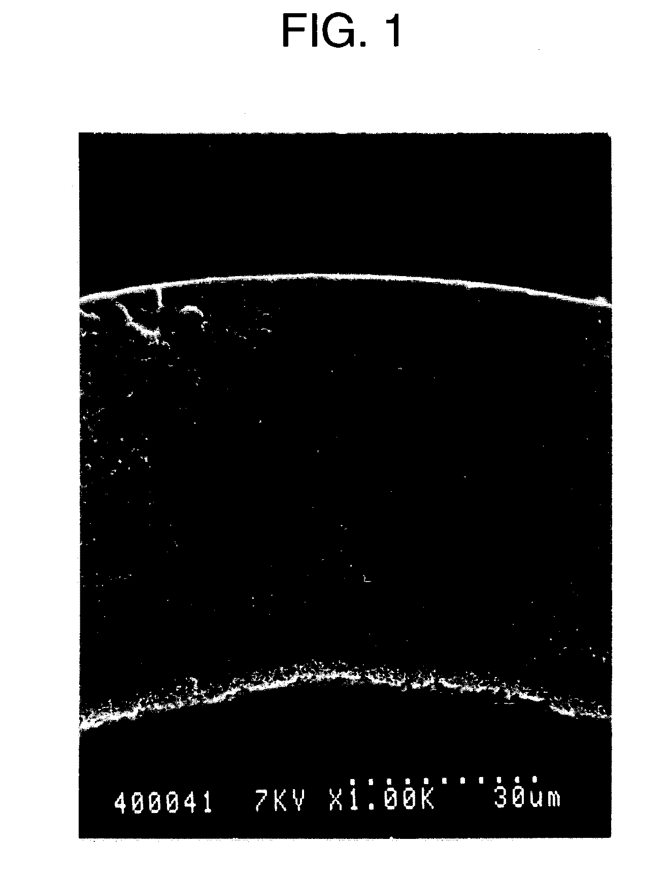
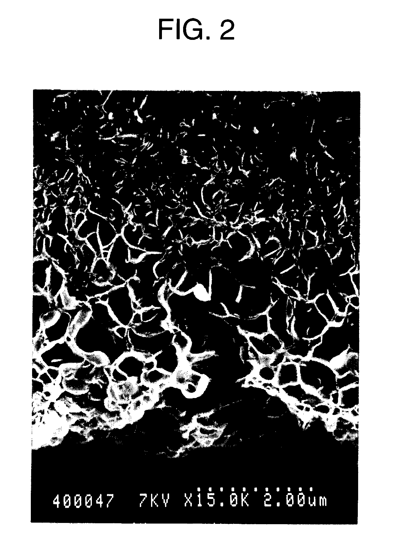
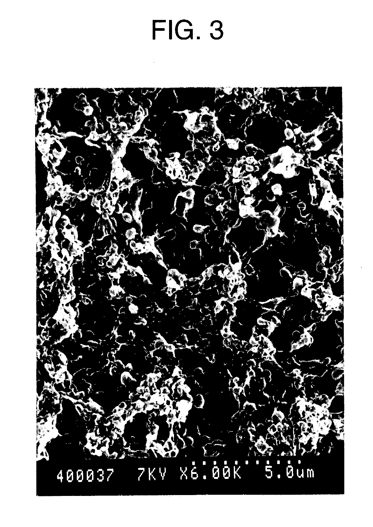
[0116]A hollow fiber like microporous membrane was obtained in accordance with Example 1 except that a polyvinylidene fluoride resin and dicyclohexyl phthalate were melt mixed to get a homogeneously dissolved solution, which was extruded in a form of hollow fiber from a spinneret at an extrusion rate of 9.5 m / min (a draft ratio of 6.3 times). A maximum pore diameter of thus obtained microporous membrane was 40 nm, and observation results of a cross-sectional structure of the membrane by a scanning electron microscope showed that a thickness of a coarse structure layer formed adjacent to an inner surface side was 9 μm and a ratio of a fine structure layer to the whole membrane thickness was 82%. Physical properties of this microporous membrane are shown in Table 2.

example 3

[0117]A hollow fiber like microporous membrane was obtained in accordance with Example 1 except that a polyvinylidene fluoride resin and dicyclohexyl phthalate were melt mixed to get a homogeneously dissolved solution, which was extruded in a form of hollow fiber from a spinneret at an extrusion rate of 5.5 m / min (a draft ratio of 10.9 times). A maximum pore diameter of the thus obtained microporous membrane was 39 nm, and observation results of a cross-sectional structure of the membrane by a scanning electron microscope showed that a thickness of a coarse structure layer formed adjacent to an inner surface side was 7 μm and a ratio of a fine structure layer to the whole membrane thickness was 84%. Physical properties of this microporous membrane are shown in Table 2.


PUM

PropertyMeasurementUnit
Temperatureaaaaaaaaaa
Fractionaaaaaaaaaa
Pore sizeaaaaaaaaaa

Abstract

A multilayer microporous membrane containing a thermoplastic resin, comprising a coarse structure layer with a higher open pore ratio and a fine structure layer with a lower open pore ratio, wherein said coarse structure layer is present at least in one membrane surface having a thickness of not less than 5.0 μm, a thickness of said fine structure layer is not less than 50% of the whole membrane thickness, and said coarse structure layer and said fine structure layer are formed in one-piece.

Description

TECHNICAL FIELD [0001]The present invention relates to a microporous membrane having a superior permeability. More particularly, the present invention relates to a microporous membrane suitable for removal of minute substances such as viruses, from a solution containing physiologically active substances such as proteins.BACKGROUND ART [0002]Recently, problems with pathogens such as viruses and pathogenic proteins, which may possibly exist as contaminants in a solution for injection, have been highlighted as a critical situation. This is especially true when a liquid preparation containing a physiologically active substance such as plasma derivatives, biopharmaceuticals or plasma for transfusion is administered into a human body. A method for removing or inactivating such pathogens is required.[0003]Methods for inactivating viruses include heating processes and treatments using chemical agents (for example solvent / detergent (S / D) treatment). However, these methods are limited in thei...

Claims


Application Information

Patent Timeline
IPC IPC(8): B01D29/01B01D67/00B01D69/02B01D69/08B01D71/34
CPCB01D67/0011B01D67/0016B01D67/0018B01D67/003B01D67/0083B01D67/0093B01D69/02B01D69/08B01D71/34B01D2325/02B01D2325/022B01D2323/385Y10T428/249961Y10T428/249979Y10T428/249978Y10T428/249958Y10T428/249964Y02A50/30
Inventor NAGOYA, FUJIHARUKOGUMA, ICHIRO
Owner ASAHI KASEI MEDICAL CO LTD
Learn More