Compound phase encoding for printed servo patterns

a technology of compound phase and servo pattern, which is applied in the direction of maintaining head carrier alignment, digital recording, instruments, etc., can solve the problems of poor performance at contemporary data densities, not well suited to printing process, and difficult to maintain complex stw in such a clean environment, so as to improve magnetic printing, improve the matching of pattern to channel chip capabilities, and reduce the variation of feature size

Inactive Publication Date: 2007-01-23
BAKER BILL RICHARD
View PDF34 Cites 33 Cited by
  • Summary
  • Abstract
  • Description
  • Claims
  • Application Information

AI Technical Summary

Benefits of technology

[0021]Another object of this invention is to improve magnetic printing by reducing variations in feature size and to better match the pattern to the channel chip capabilities.
[0022]Another objective is to reduce the area required for the printed pattern so that it can be used directly as the final servo pattern without rewriting in a SSW mode.

Problems solved by technology

It is expensive and difficult to maintain the complex STW in such a clean environment.
Direct printing of a conventional edge of burst servo pattern resulted in poor performance at contemporary data densities, (Ishida, et al., “Demodulation of servo tracking signals printed with a lithographically patterned master disk”, IEEE Trans.
The conventional Gray codes would provide the absolute radial position, but they are not well suited to the printing process and result in fuzzy transitions at track edges.
Unfortunately those codes occupy a large part of the surface, they are not well adapted to the architecture of commercial channel chips, and they require larger variations of widths of lines and spaces.
The large variations of feature sizes exacerbate noise sources of the printing process.
Because the printing method involves several processes such as optical diffraction, diffusion in the photo resist, and shadowing during sputtering of the cobalt, it is difficult to produce square corners or small radii of curvature at the ends of the cobalt lines.
This contact magneto-optic method also has limitations due to diffraction and to the difficulty of maintaining the small space between reticle and slave disk and due to reflections between the two.
Using an antireflective coating on the reticle is difficult because the energy density of the laser irradiation damages the coating.
It is also well known that fields at the edges of conventional write heads are poorly controlled, (Van Herk, “Analytical expressions for side fringing response and crosstalk with finite head and track widths”, IEEE Trans.
Therefore the STW and the SSW method both introduce noise at edges of bursts of conventional final servo patterns.
That noise becomes a greater problem at extremely high track densities.

Method used


Image

  • Compound phase encoding for printed servo patterns
  • Compound phase encoding for printed servo patterns
  • Compound phase encoding for printed servo patterns

Examples


embodiment

PREFERRED EMBODIMENT

[0071]The previous methods using relatively prime numbers of sub intervals could be decoded more easily when the numbers of sub intervals were about the same for all higher order bursts. However, errors in measurements of the phase angles are nearly independent of the pitch of the bursts, and that allows use of an encoding method similar to positional number systems such as our conventional decimal notation.

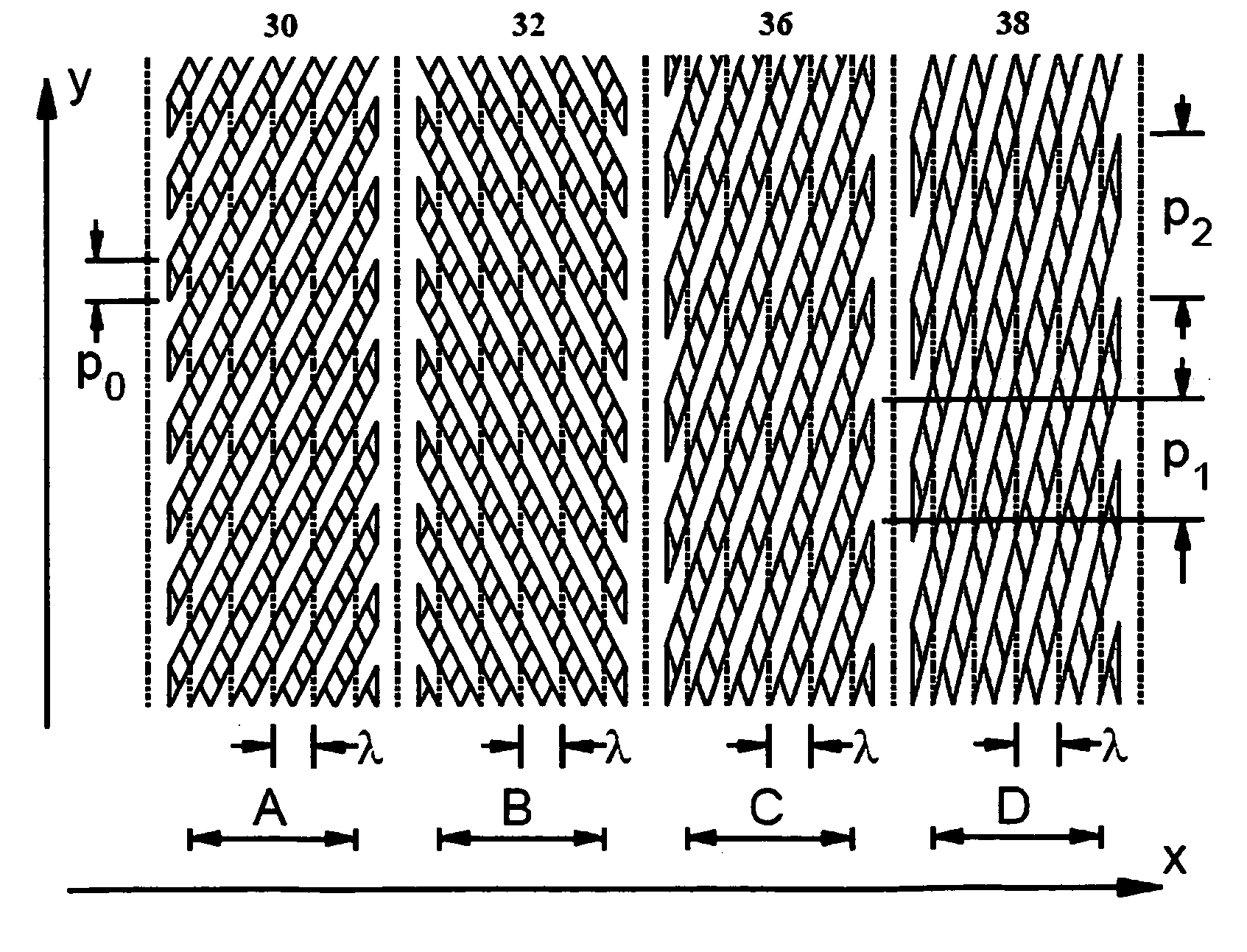
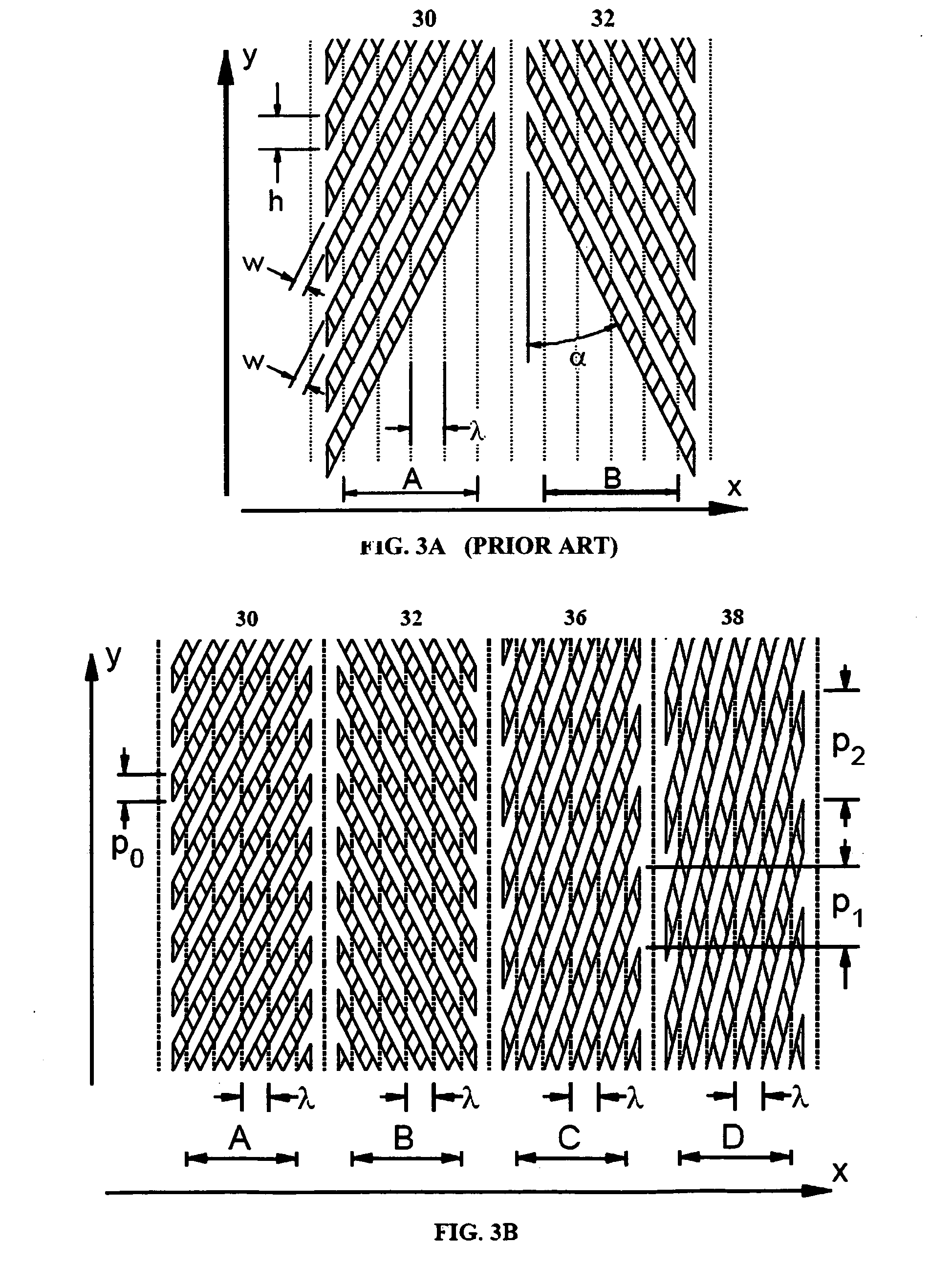
[0072]As a simple example let the first higher order burst have a pitch R times the fundamental pitch p0. Then R sub intervals can be accurately identified in each cycle. Let the pitch of the next burst be R*R times p0. For each additional more significant burst let its pitch be R times that of its predecessor. The 2π phase range of each burst can be accurately divided into R equal phase segments that each identify one cycle of the preceding, less significant burst. If there are Q of such higher order bursts, and if the segment indices, kq, are measured for ea...


PUM

PropertyMeasurementUnit
thickaaaaaaaaaa
feature sizesaaaaaaaaaa
timeaaaaaaaaaa

Abstract

A type of servo pattern suitable for tracking systems in magnetic recording devices such as floppy disks or linear tape or hard disks or in other machines. The pattern comprises several phase-encoded elements that provide an absolute transverse position coordinate from local data. Computations can be made with channel chips commonly used in magnetic recording disk drives.

Description

CROSS-REFERENCE TO RELATED APPLICATIONS[0001]This application claims priority from U.S. Provisional Patent Application No. 60 / 447,442 filed Feb. 14, 2003, the entire disclosure of which is incorporated herein by reference, and International Application No. PCT / US 03 / 41733 filed Dec. 31, 2003.FEDERALLY SPONSORED RESEARCH[0002]Not ApplicableSEQUENCE LISTING OR PROGRAM[0003]Not ApplicableBACKGROUND OF THE INVENTION[0004]1. Field of the Invention[0005]This invention relates to printing or rapidly transferring fixed servo reference data to surfaces such as those of magnetic storage media and, more particularly, to printing servo data with compound phase patterns that provide absolute position information, that are well suited to commercial data channel chips, and that require relatively little space on the recording surface.[0006]2. Description of the Prior Art[0007]Modern magnetic recording systems have servo information or position markers written in an interleaved fashion on the same ...

Claims


Application Information

Patent Timeline
Patent Type & Authority Patents(United States)
IPC IPC(8): G11B5/02G11B5/09G11B5/584G11B5/596G11B5/86
CPCB82Y10/00G11B5/584G11B5/865G11B5/5965G11B5/743G11B5/59633
Inventor BAKER, BILL RICHARD
Owner BAKER BILL RICHARD
Why Eureka
Try Eureka