Film bulk acoustic wave resonator

a resonator technology, applied in the field of film bulk acoustic wave resonators, can solve the problems of spurious bulk waves, general inferiority of diaphragm type smr type smr type in resonance characteristics, etc., to achieve the effect of reducing undesired reflections from the substrate, increasing adhesion, and elevating the crystallinity of the lower electrod

Active Publication Date: 2007-02-06
SNAPTRACK
View PDF6 Cites 18 Cited by
  • Summary
  • Abstract
  • Description
  • Claims
  • Application Information

AI Technical Summary

Benefits of technology

[0007]It is therefore an object of the present invention to provide an SMR type film bulk acoustic wave resonator having an improved acoustic multilayer that improves the resonance characteristics.
[0010]Thus providing at least one of the reflective films of the acoustic multilayer with a specified crystal plane orientation makes it possible to increase the efficiency with which bulk waves propagating towards the substrate are reflected, thereby making it possible to reduce undesired reflections from the substrate compared to the prior art. As a result, compared to the prior art, better resonance characteristics can be obtained.
[0011]The X-ray rocking curve full width at half maximum (FWHM) of the at least one reflective film is preferably not greater than 10 degrees, and more preferably is not greater than 3 degrees. This is because the higher the crystallinity of the reflective film, the higher the bulk wave reflection efficiency and the impedance ratio become.
[0013]When the reflective film having the specified crystal plane orientation has a cubic crystal structure such as aluminum nitride (AlN), zinc oxide (ZnO) and aluminum oxide (Al2O3), it is preferable for the specified crystal plane to be a (0001) plane. When the reflective film having the specified crystal plane orientation has a face-centered cubic crystal structure such as tungsten (W) and molybdenum (Mo), it is preferable for the specified crystal plane to be the (110) plane. This is because materials having a cubic crystal structure are readily oriented in the (0001) plane, and materials having a face-centered cubic structure are readily oriented in the (110) plane.
[0014]The resonant structure preferably includes a piezoelectric film provided between the upper and lower electrodes, and preferably further includes an adhesion orientation control film provided between the acoustic multilayer and the lower electrode. When the adhesion orientation control film is provided as the base of the lower electrode, it increases the adhesion between the lower electrode and the acoustic multilayer and elevates the crystallinity of the lower electrode.
[0015]Thus, in accordance with this invention, undesired reflections from the substrate are reduced, making it possible to provide a film bulk acoustic wave resonator having good resonance characteristics with low spuriosity, and it is also possible to achieve a high impedance ratio.

Problems solved by technology

However, SMR type film bulk acoustic wave resonators are known to be generally inferior to the diaphragm type concerning resonance characteristics.
This is because the air interface on both sides of the resonant structure in the case of the diaphragm type enables relatively free resonance, while in the case of the SMR type, bulk waves propagated on the substrate side that are not adequately reflected by the acoustic multilayer reach the substrate and are reflected thereby, giving rise to spurious bulk waves.

Method used


Image

  • Film bulk acoustic wave resonator
  • Film bulk acoustic wave resonator
  • Film bulk acoustic wave resonator

Examples


example 1

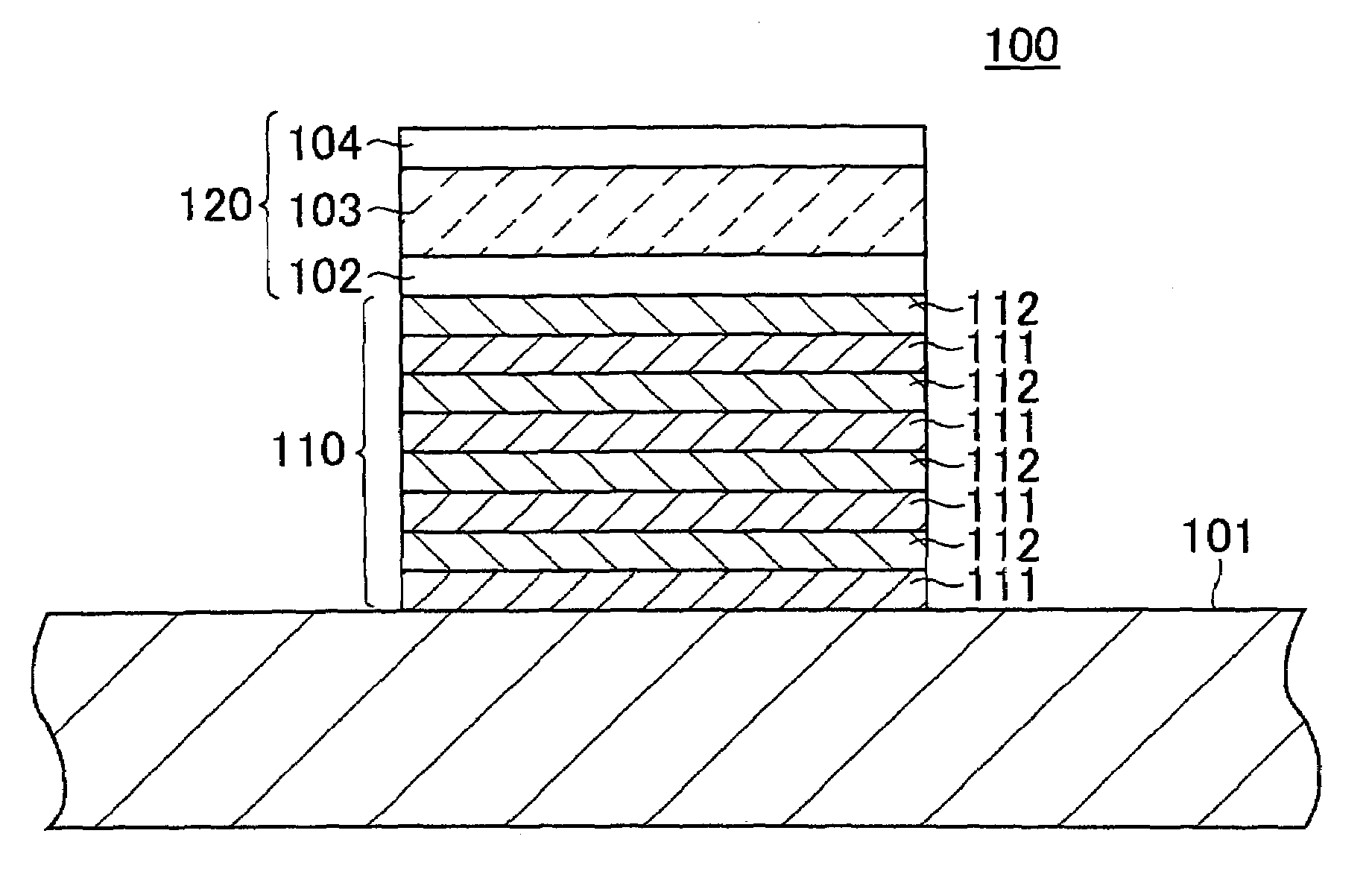
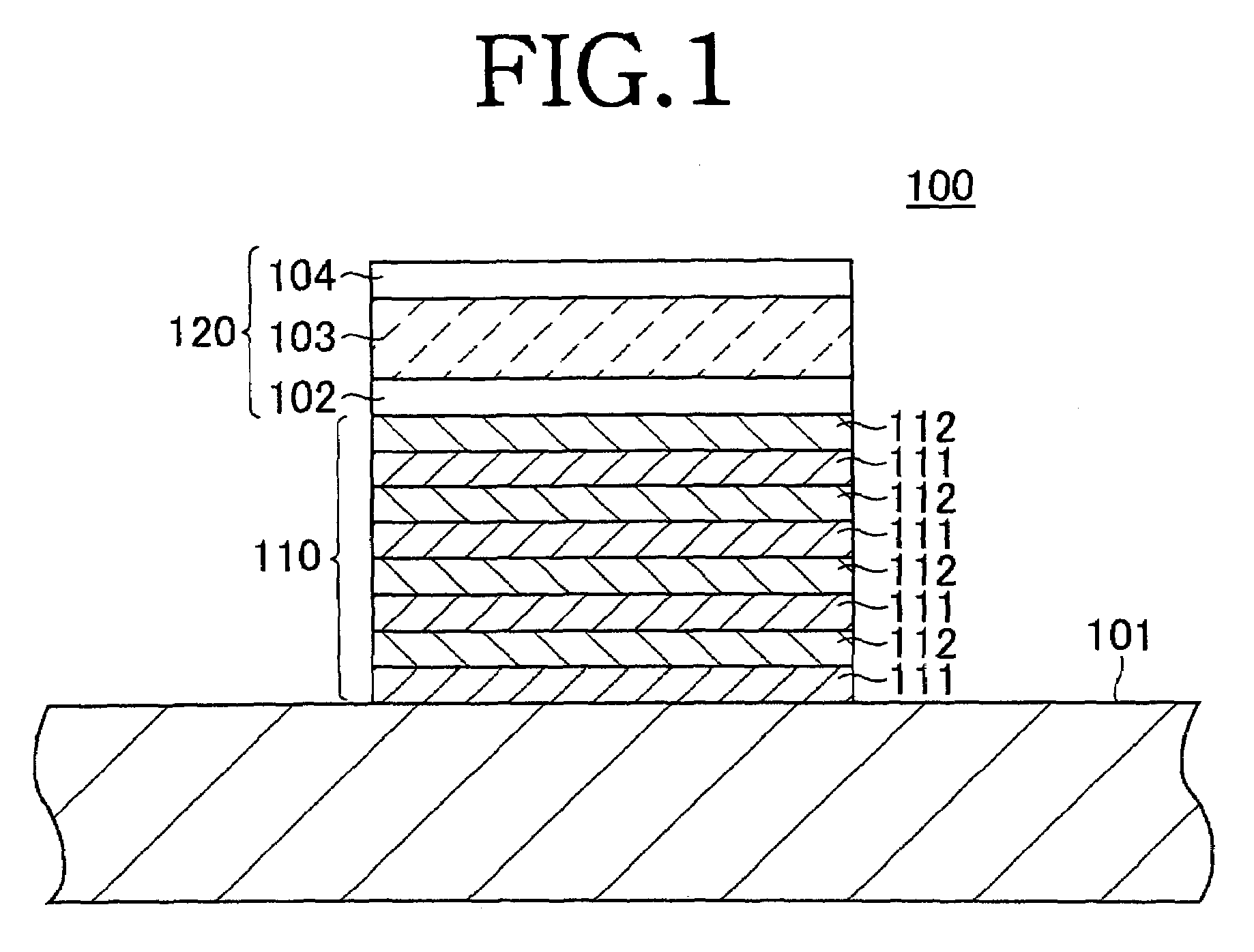
[0053]In Example 1, a number of film bulk acoustic wave resonators having the structure of the film bulk acoustic wave resonator 100 shown in FIG. 1 were fabricated by the following method.

[0054]First, a Si (100) substrate 101 composed of mirror-polished Si single crystal and having a thickness of 250 μm and a resistivity of 1000 Ω·cm was prepared and washed. Next, the acoustic multilayer 110 was formed by repeating four cycles of a process in which a first reflective film 111 made of 1.5 μm thick AlN film formed by RF magnetron sputtering and a second reflective film 112 made of an 0.8 μm thick SiO2 film formed by RF magnetron sputtering were alternately overlaid in this order.

[0055]The first reflective film 111 was formed by sputtering, using aluminum (Al) as the target and an 80:20 mixture of argon (Ar) and nitrogen (N2) as the sputter gas. The chamber pressure was set at 0.5 Pa and the sputter temperature at 80° C.

[0056]The second reflective film 112 was formed by sputtering, us...

example 2

[0062]The film bulk acoustic wave resonator of Example 2 was formed in the same way as in Example 1, except that the first reflective film 111 was formed using a 50:50 mixture of argon (Ar) and nitrogen (N2).

[0063]Measurement of the X-ray rocking curve of the aluminum nitride (AlN) first reflective film 111 of the film bulk acoustic wave resonator of Example 2 thus fabricated confirmed a strong peak in the (0001) plane; the rocking curve FWHM was approximately 10 degrees.

[0064]Next, the measuring instrument was connected to the film bulk acoustic wave resonator of Example 2 to measure the actual resonance characteristics. The measurement results are shown in FIG. 4.

[0065]As shown by FIG. 4, there were very few spurious readings caused by reflections from the substrate 101 of the film bulk acoustic wave resonator of Example 2. However, the impedance ratio was lower than in the case of the film bulk acoustic wave resonator of Example 1, which might be due to the different crystallinit...


PUM


Abstract

A film bulk acoustic wave resonator of the invention includes a substrate; a resonant structure provided on the substrate constituted by a lower electrode, a piezoelectric film and an upper electrode; and an acoustic multilayer of a plurality of reflective films provided between the substrate and the resonant structure. At least one of the reflective films of the acoustic multilayer has a specified crystal plane orientation, and an X-ray rocking curve full width at half maximum that is preferably not greater than 10 degrees, and more preferably is not greater than 3 degrees. This makes it possible to obtain better resonance characteristics than in the case of the prior art, by increasing the efficiency with which bulk waves propagating towards the substrate are reflected.

Description

TECHNICAL FIELD[0001]The present invention relates to a film bulk acoustic wave resonator, and particularly to a solidly mounted resonator (SMR) type film bulk acoustic wave resonator having an acoustic multilayer.BACKGROUND OF THE INVENTION[0002]In recent years, various resonators using piezoelectric materials such as a film bulk acoustic wave resonator (FBAR) and a surface acoustic wave (SAW) resonator have come into practical use as small and high-performance resonators. Especially, the film bulk acoustic wave resonator has been recently attracting attention in view of uses where a high resonant frequency such as GHz band is required, because the resonant frequency thereof is easily increased due to its structure compared to the surface acoustic wave resonator.[0003]As described in Japanese Patent Application Laid Open No. 10-270979, the film bulk acoustic wave resonator is basically constituted of an upper electrode, a lower electrode and a piezoelectric film interposed therebet...

Claims


Application Information

Patent Timeline
Patent Type & Authority Patents(United States)
IPC IPC(8): H01L41/08H03H9/54H01L41/18H01L41/09H01L41/22H01L41/29H01L41/319H03H9/02H03H9/17
CPCH03H9/02094H03H9/176H03H9/175
Inventor SAITO, HISATOSHINOGUCHI, TAKAOINOUE, KENJI
Owner SNAPTRACK
Why Eureka
Try Eureka