E×B ion detector for high efficiency time-of-flight mass spectrometers

a mass spectrometer and high-efficiency technology, applied in mass spectrometers, particle separator tubes, electric multiplier tubes, etc., can solve the problems of inability to obtain sufficient high time resolution for a tofms, ions with close by mass will hit the detecting surface, and distortion of the electric field seen by ions. , to achieve the effect of improving detection efficiency and time resolution

Active Publication Date: 2007-02-20
EL MUL TECH
View PDF3 Cites 19 Cited by
  • Summary
  • Abstract
  • Description
  • Claims
  • Application Information

AI Technical Summary

Benefits of technology

[0012]In view of the above, it is an object to provide a detector for a TOFMS with improved time resolution and improved detection efficiency.
[0016]a converter assembly comprising a planar electrically conducting converter plate and a converter member for providing efficient conversion of impacting heavy ions to secondary electrons, said converter member being supported by said converter plate, and said converter plate being easily replaceable;
[0020]It will be appreciated that the above design has significant advantages with respect to the device of Byrd et al. The number of meshes is decreased by one, because of the combination of the magnetic field and the electrical field in the same section of the path of the electrons. This results in an improved electron transmission. Moreover, the overall dimensions may be more compact, since no additional acceleration path is required for the electrons, before they enter the magnetic field.
[0021]According to one embodiment of the invention, the converter plate and the exit plate are arranged in one plane. This means also that they are on the same electrical potential. In this embodiment the converter plate and the exit plate may be provided as a single integral plate. In this design it is presently desired that the electron detection assembly provides an electrical field which leaks through the exit window in order to draw the arriving electrons therethrough. This is advantageous in order to limit the influence of the variation in emission energy of the electrons from the converter member on the time spread of the electrons passing through the exit window.
[0026]Said converter plate is integrated into the assembly such that it can be easily replaced by the MSTOF user, once the conversion efficiency has been reduced too much by the ion bombardment. Thus full detection efficiency can be restored by an easy and cost effective replacement of a consumable, rather than the replacement of a full detector.
[0030]According to a still further aspect of the invention, pertaining to an embodiment wherein the electron detection assembly comprises an MCP-type detector, and wherein the plane of the exit plate is spaced apart from the plane of the entrance plate, the MCP-type detector is provided within the E×B field such that the secondary electrons impinge at its surface at the optimal energy for detection, typically some 200–500 eV. In this case the mesh in front of the secondary electron detector is not necessary and thus both overall transmission and detection efficiency for secondaries are improved.

Problems solved by technology

The efficient detection of these ions at the end plane with a time resolution sufficient to separate adjacent mass ions, even when the quantities of the adjacent ions vary, is a critical issue in the performance in any TOFMS.
Otherwise, there is a risk that ions with close by masses will hit the detecting surface at the same time.
Also, some distortion of the electric field seen by the ions may be introduced effecting their arrival time to the detecting plate.
Thus, sufficiently high time resolution for a TOFMS cannot be obtained.
As discussed above an MCP provides only limited efficiency, since for MCP 45% of the electrons that reach an MCP do not generate a signal.
Additionally, every screen to be passed reduces the detection efficiency by 10–20% and generates secondary particle background.

Method used


Image

  • E×B ion detector for high efficiency time-of-flight mass spectrometers
  • E×B ion detector for high efficiency time-of-flight mass spectrometers
  • E×B ion detector for high efficiency time-of-flight mass spectrometers

Examples


Embodiment Construction

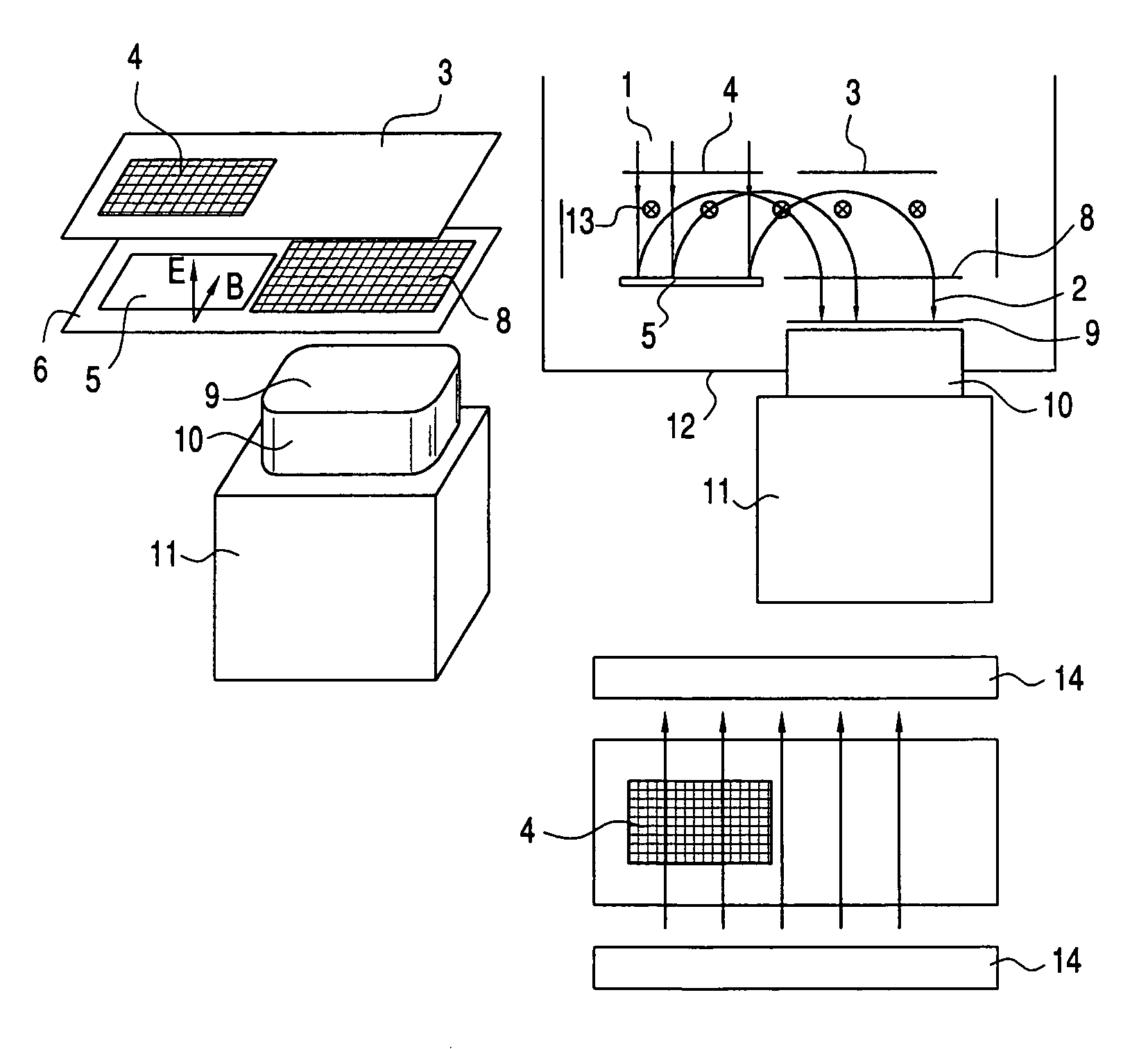
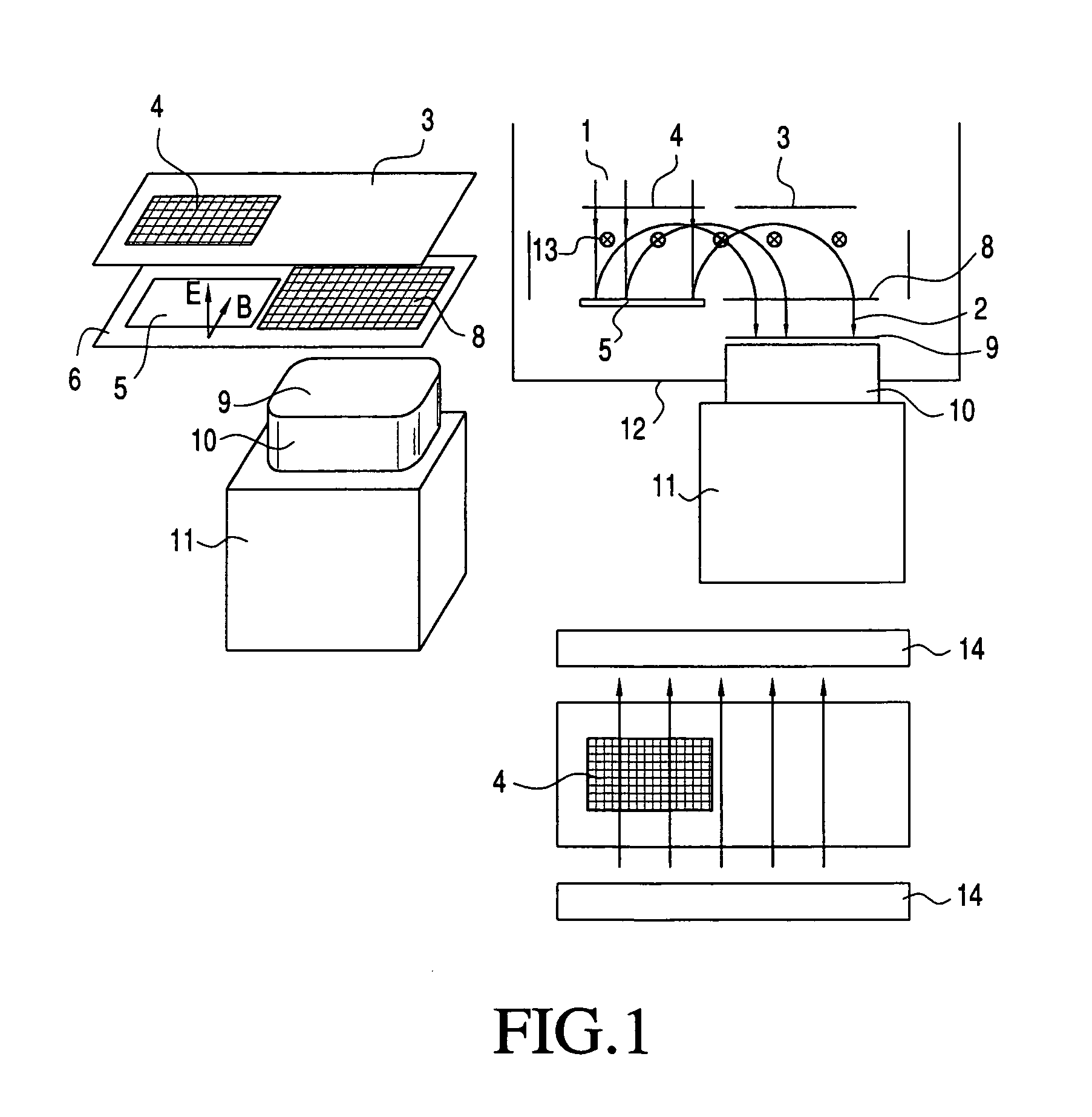
[0034]The ion detector for a TOFMS shown in FIG. 1, comprises a planar conducting entrance plate 3, said entrance plate comprising a first window with first a highly transparent metallic mesh 4. The transparent mesh is aligned with the trajectory of incoming ions 1, wherein the entrance plate 3 is oriented perpendicular to the axis of the ion beam. Typical transparency of the mesh can reach 90%. The mesh 4 is at the same potential V1 as the potential of a traveling tube of the ions (not shown). The ion detector further comprises a planar conducting conversion plate 6, wherein the conversion plate 6 comprises a converter member 5, which is aligned with the highly transparent metallic mesh 4. The planar converter member 5 comprises a material that has high electron emission probability per impinging ion such as CVD diamond or oxides or other materials known for their high secondary emission coefficients. The metallic mesh (4) and the converter member 5 subtend the area of the incoming...


PUM


Abstract

An ion detector having a planar electrically conducting entrance plate, a converter assembly including a planar electrically conducting converter plate and a converter member for providing free electrons upon impact of ions, a planar electrically conducting exit plate having an exit window, a magnet assembly, and an electron detection assembly. The planes of the converter plate and the entrance plate are parallel and electrically biasable in order to provide a homogeneous electric field. The magnet assembly provides a homogenous magnetic field between the converter plate and the exit plate, the magnetic field extending parallel to the plane of the converter plate. The ratio between the electric and the magnetic field is such that the electrons emitted from the converter plate travel to the exit window and are detected by the electron detection assembly.

Description

[0001]This application claims the benefit of Domestic Priority under 35 U.S.C. § 119(e) based upon Provisional Application No. 60 / 590,533, filed Jul. 29, 2003.FIELD OF THE INVENTION[0002]Time-of-flight mass spectrometers (TOFMS) are used to identify the masses of very heavy molecular ions or clusters with masses reaching to several hundred thousand atomic mass units. Various techniques (e.g. MALDI) allow to generate low charge very heavy organic molecules or clusters. All these charged species will be denoted as ions. Typically in TOFMS a very short (sub ns) pulsed injection of the ions is accelerated to 2–30 kV and allowed to fly one to several meters in a straight line usually with an electrostatic reflector to add a return path to shorten the physical size of the instrument and to sharpen the time distribution.BACKGROUND OF THE INVENTION[0003]The time of arrival of the ions at an end plate is directly related to their M / q (mass to charge state ratio). In a typical application (10...

Claims


Application Information

Patent Timeline
Patent Type & Authority Patents(United States)
IPC IPC(8): H01J49/00H01J49/02H01J49/10H01J49/40
CPCH01J49/40H01J49/025
Inventor CHEFETZ, ELISCHON, ARMIN
Owner EL MUL TECH
Why Eureka
Try Eureka