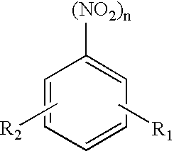
Process for the production of aromatic amines by heterogeneously catalysed hydrogenation

a technology of aromatic amines and hydrogenation, which is applied in the preparation of organic compounds, amino-hyroxy compounds, organic chemistry, etc., can solve the problems of low specific loading of catalysts, affecting the effective dissipation of heat in this method, and unsatisfactory space-time yield in industrial-scale processes. , to achieve the effect of increasing the service life of the isothermal main reactor, increasing the space-time yield, and large hydrogen excess

Inactive Publication Date: 2007-03-20
BAYER MATERIALSCIENCE AG
View PDF13 Cites 2 Cited by
  • Summary
  • Abstract
  • Description
  • Claims
  • Application Information

AI Technical Summary

Benefits of technology

[0017]The particular advantage of the dip-coating process is that a thin layer of a catalytically active component can be applied comparatively easily on to a monolithic support. With the dip-coating process, a catalytically active coating with a film thickness of no more than 250 μm, preferably of no more than 100 μm, and particularly preferably of 10 to 100 μm, can be applied on to the monolithic support. The dip coating can be performed one or more times. By repeated coating, monolithic supports with a catalytically active material, consisting of support substance and catalytically active component, especially up to no more than 150 g / l, preferably of 30 to 150 g / l, and more preferably of 50 to 120 g / l, of monolithic support can be produced.
[0018]The process according to the invention is suitable to be carried out on an industrial scale. This process exhibits a higher space-time yield and longer service life compared with the processes known from the prior art, particularly those processes carried out in shell-and-tube reactors.
[0019]The catalyst of the present invention for the process of producing aromatic amines, consisting of a monolithic support and a catalytically active coating, displays considerable advantages compared with conventional catalyst beds which are known and described in the prior art. On the one hand, the pressure drop of monolithic supports is substantially lower than that of catalyst beds for a comparable flow-through velocity. Conversely, much higher flow velocities are possible through the monolithic support for the same pressure drop. As a result of the low pressure drop, even at very high flow velocities, the use of monolithic supports is advantageous, for example, for use in downstream reactors or in processes that are distinguished by high volume flows and flow velocities. At the same time, substantially more compact reactors can be built with these catalysts. Another advantage is based on the very thin catalytically active coating. If the catalytically active components are deposited in a very thin layer, the influence of diffusion is much smaller than in the case of full catalysts. In addition, if the main reaction is accompanied by secondary reactions, a higher selectivity can be achieved with these very thin catalytically active coatings. Application in a thin layer can also provide advantages in terms of selectivity for valuable products.
[0028]The production of aromatic amines can also be carried out by the process according to the invention in a two-step or a multi-step process. In the two-step embodiment of the process, the reaction is carried out first, for example, in an isothermally operated, thermostatically controlled main reactor, with a stationary catalyst bed, wherein the degree of conversion can be 80% to 100%. As mentioned e.g. in DE-A 28 49 002, believed to correspond to U.S. Pat. No. 4,265,834, the disclosure of which is hereby incorporated by reference, and WO 98 / 46557, believed to correspond to U.S. Pat. No. 6,080,890, the disclosure of which is hereby incorporated by reference, the hydrogenation of nitroaromatics is accompanied by coking of the catalyst. In reactors with a stationary catalyst bed, this leads to a break-through of the bed. From this point, the nitroaromatics can no longer be 100% converted due to the deactivation of the catalyst bed. The downstream, adiabatically operated secondary reactor is utilised to complete the conversion to 100% when the rate of conversion in the main reactor is less than 100%. By using the adiabatic secondary reactor, the service life of the isothermal main reactor can be increased. Thus, the present invention is particularly advantageous in association with the retrofitting of existing thermostatically controlled shell-and-tube reactors with the goal of increasing the space-time yield.
[0029]In another preferred embodiment the process is a two-step process, with an isothermally operated, thermostatically controlled main reactor-with a stationary catalyst bed being used in the first step and an adiabatically operated secondary reactor with a catalyst comprising a monolithic support in the second step. Here, the catalyst bed in the main reactor is diluted with inert material. The dilution of the catalyst bed with inert material enables the catalyst loading to be increased, as described for example in WO 98 / 46557, believed to correspond to U.S. Pat. No. 6,080,890, the disclosure of which is hereby incorporated by reference. As a diluting material (inert material), for example, the inert catalyst support of the catalyst bed or other inert fillers of glass, ceramic or metal can be used. Substances with high thermal conductivity are preferably used. The catalyst is generally diluted with 10 to 50 vol. % inert material, and preferably with 20 to 40 vol. % inert material. However, as a result of diluting the bed, the service life of the reactor decreases as there is less active catalyst in the reaction volume. This loss of service life can be compensated for by the use of an adiabatically operated secondary reactor. Through the combination of a diluted catalyst bed in a main reactor and an adiabatic secondary reactor, the productivity of the overall process can be increased. This process is especially suitable for existing reactors. By using the monolithic support with a very low pressure drop, the secondary reactor can be integrated into the existing reaction circulation without any problems. With the monolithic support, e.g. honeycomb, it is even possible to achieve flow velocities of more than 10 m / s, for example, in the secondary reactor. This results in the possibility of reducing the residence times in the secondary reactor to values of less than 1 s. Therefore, the selectivity of the main reactor is scarcely affected by secondary reactions in the secondary reactor. Thus, the capacity of existing reactors for the hydrogenation of nitroaromatics can be increased at very low cost by retrofitting an adiabatic secondary reactor with a monolithic catalyst.

Problems solved by technology

The effective dissipation of heat in this method is impeded by problems resulting from the non-uniform residence time distribution (break-through of the nitroaromatics) and from catalyst abrasion.
One disadvantage in the gas phase hydrogenation described in DE-A 28 49 002 is the low specific loading of the catalysts.
Associated with the low catalyst loading is an unsatisfactory space-time yield in industrial-scale processes for the production of aromatic amines.
Moreover, the selectivities at the beginning of a run period are distinctly lower than towards the end, which leads to losses of yield and problems in working up the crude product.
As a result of the dilution, however, the service life of the bed decreases.

Method used


Image

  • Process for the production of aromatic amines by heterogeneously catalysed hydrogenation
  • Process for the production of aromatic amines by heterogeneously catalysed hydrogenation

Examples


example 1

Production of Catalytically Coated Monolithic Honeycombs

[0031]Cylindrical honeycombs of cordierite with a length of 152 mm, a diameter of 30.5 mm and a cell density of 400 cpsi were used as monolithic supports. The monolithic supports were cleaned, dried and weighed before coating. The composition of the supported, catalytically active components used as the catalytically active coating was as follows: 9 g palladium, 9 g vanadium and 3 g lead per liter of spherical alpha-aluminium oxide. (A detailed description of the supported catalyst can be found in DE-A 28 49 002, believed to correspond to U.S. Pat. No. 4,265,834, the disclosure of which is hereby incorporated by reference.) From these supported, catalytically active components, a powder with a particle size of d50.3=1.7 μm and d90.3=4.9 μm was produced by comminution and extremely fine grinding prior to coating.

[0032]For the coating suspension, a solution of 3.2 g of 25 wt. % aqueous ammonium polymethacrylate solution (“Darvan ...

example 2

Standard Bed (Comparative Example)

[0036]A tubular reactor thermostatically controlled with oil, having an internal diameter of 26 mm and a length of 3000 mm, was filled with a catalyst as described in DE-A 28 49 002 which is believed to correspond to U.S. Pat. No. 4,265,834, the disclosure of which is hereby incorporated by reference. A protective tube with a mobile thermocouple was located in the center of the tubular reactor to detect the temperature in the catalyst bed. The catalyst was flushed first with nitrogen and then with hydrogen, and was then activated with 1,000 l / h hydrogen at 240° C. over a period of 49 h.

[0037]Nitrobenzene was then evaporated in a mixture of nitrogen and hydrogen. The nitrobenzene loading was slowly increased from 134 g / h to the maximum value of 690 g / h in such a way that the maximum temperature in the bed did not rise above 460° C. In this phase, an 820 l / h volume flow of the mixture was passed through the reaction tube, maintaining a 4 to 1 molar ra...

example 3

Use of the Monolithic Honeycomb (Example of an Embodiment)

[0039]Monolithic honeycombs produced according to Example 1 were used as catalysts in a tubular reactor thermostatically controlled with oil, having an internal diameter of 32.8 mm. Five (5) honeycombs, each with a length of 150 mm and a diameter of 30.5 mm, were introduced into the reaction tube. The active catalyst material deposited on these 5 honeycombs i.e. support substance and catalytically active component, totalled 37.5 g. The gap between the tube wall and the honeycomb was sealed with a heat-resistant fleece (Carborundum, type FT 1). A protective tube with a mobile thermocouple was located in the center of the tubular reactor to detect the temperature in the monolithic honeycomb. The catalyst was flushed first with nitrogen and then with hydrogen, and was finally activated with 500 l / h hydrogen at 300° C. over a period of 3 h.

[0040]Nitrobenzene was then evaporated in a mixture of nitrogen and hydrogen. The nitrobenz...


PUM

PropertyMeasurementUnit
temperatureaaaaaaaaaa

Abstract

The invention describes a process for the production of aromatic amines by the catalytic hydrogenation of aromatic nitro compounds, with the process being characterized by at least one catalytic hydrogenation step and the catalyst consists at least of a monolithic support and a catalytically active coating.

Description

BACKGROUND OF THE INVENTION[0001]The invention relates to a process for the production of aromatic amines by the catalytic hydrogenation of aromatic nitro compounds.[0002]Aromatic amines are important intermediates, which have to be produced at low cost and in large quantities. Production plants for aromatic amines are therefore generally constructed for very large capacities. The hydrogenation of nitro-aromatics is a strongly exothermic reaction. The dissipation and energy utilisation of the heat of reaction is therefore an important factor in the production of nitroaromatics.[0003]Various reactors are suitable for the gas phase hydrogenation of nitroaromatics. Thus, for example, in U.S. Pat. No. 3,136,818, a process is described in which the reaction is carried out in a fluidised bed. The effective dissipation of heat in this method is impeded by problems resulting from the non-uniform residence time distribution (break-through of the nitroaromatics) and from catalyst abrasion.[00...

Claims


Application Information

Patent Timeline
Patent Type & Authority Patents(United States)
IPC IPC(8): C07C209/36C07B61/00C07C211/46
CPCC07C209/36C07C211/46
Inventor LEHNER, PETERTUREK, THOMASBRANDT, MATTHIASBUCHHOLZ, SUSANNE
Owner BAYER MATERIALSCIENCE AG
Why Eureka
Try Eureka