
Method and apparatus for in situ depositing of neutral Cs under ultra-high vacuum to analytical ends

a neutron cs and ultra-high vacuum technology, applied in the field of new secondary ion mass spectroscopy, can solve the problems of inability to optimise analysis, inability to quantify measurements with difficulty, and inability to achieve high-efficiency measurements

Active Publication Date: 2007-04-17
CENT RECH PUBLIC GABRIEL LIPPMANN
View PDF2 Cites 2 Cited by
  • Summary
  • Abstract
  • Description
  • Claims
  • Application Information

AI Technical Summary

Benefits of technology

"The present invention relates to a method for modifying the electronic properties of a surface for analytical purposes, particularly using a neutral cesium (Cs0) deposition column. The method involves a continuous adjustment of the deposition rate of Cs0 using a temperature adjustment of the evaporator and an aperture control of the obturator. The invention also includes a method for simultaneously optimizing the deposition rate and analytical characteristics, such as depth resolution, by decoupling the deposition and sputtering phases during analysis in the MCsx+ mode. The invention further enables the use of a chemical element other than Cs, such as Mn−, Mm+, or Csxn+, to create secondary emissions for analytical purposes. The invention also includes an energy and mass analyzer instrument and a neutral cesium column for use in an analytical instrument. The technical effects of the invention include improved sensitivity and resolution of secondary emissions, optimized deposition rate, and simultaneous optimization of deposition rate and analytical characteristics."

Problems solved by technology

Alongside all its advantages, however, the SIMS technique suffers from one major drawback: the measurements can only be quantified with difficulty.
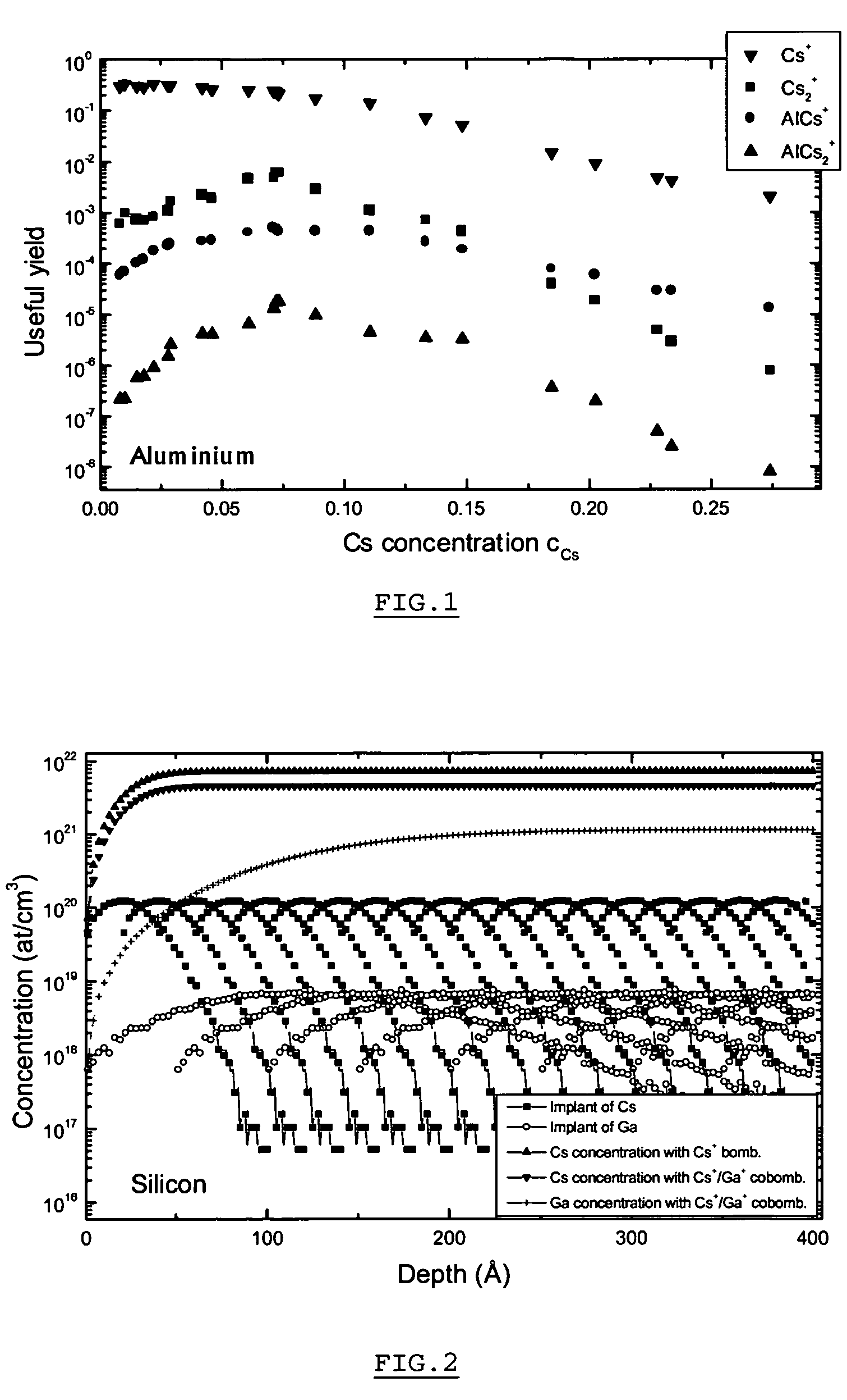
As it is unlikely that the Cs concentration thus obtained will coincide with the optimum concentration for the material in question, the analysis is not optimised.
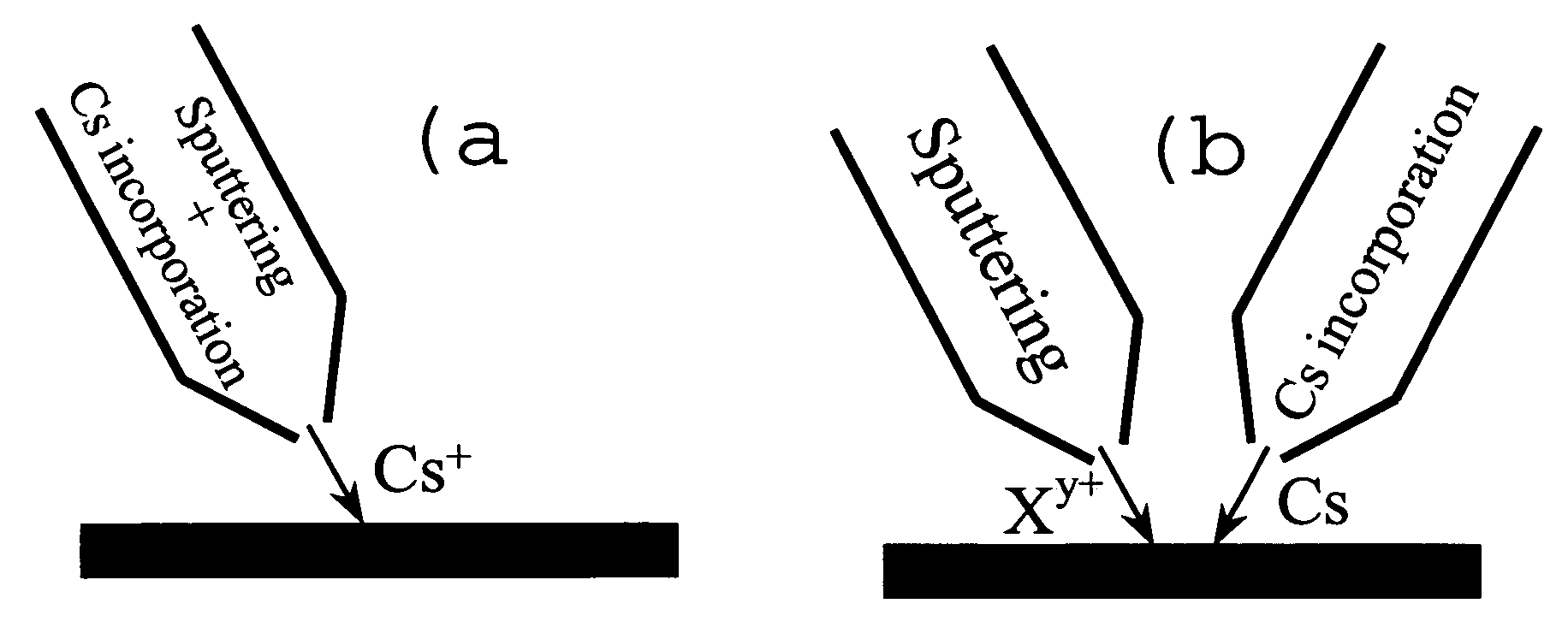
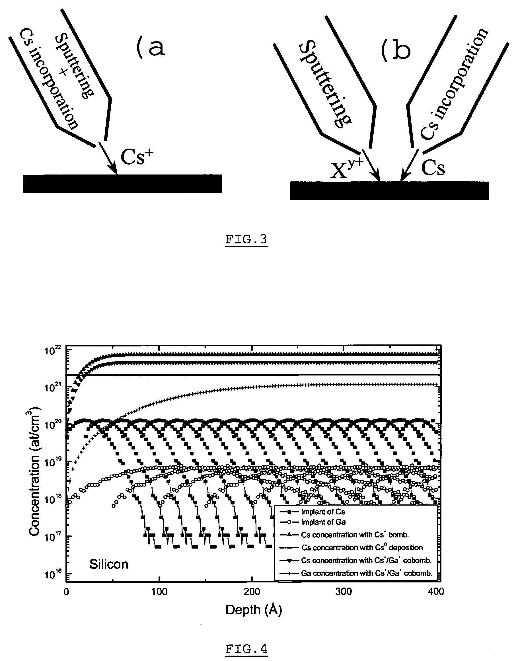
A second major disadvantage of the use of Cs+ ion bombardment relates to the impossibility of separately choosing the Cs concentration (cCs) implanted in the sample and the energetic and angular parameters of the primary beam, given that the latter determine the value of cCs.

Method used


Image

  • Method and apparatus for in situ depositing of neutral Cs under ultra-high vacuum to analytical ends
  • Method and apparatus for in situ depositing of neutral Cs under ultra-high vacuum to analytical ends
  • Method and apparatus for in situ depositing of neutral Cs under ultra-high vacuum to analytical ends

Examples


Embodiment Construction

1. The Cs0 Evaporator

1.1. Operating Principle

[0065]To deposit alkaline metals, laboratories almost exclusively use getters, marketed by the Italian group SAES, containing the alkaline metal X in the form of chromate X2CrO4 and a ZrxAly type powder acting as a reducing agent in order to release the X (i.e. Cs) atoms. When this mixture is heated by circulating an electric current, the reduction reaction is activated and the quantity of alkaline atoms thus produced depends on the heating power. In the case of Cs, this reduction reaction is written as follows:

2 Cs2CrO4+2.5 Zr→Cr2O3+2.5 ZrO2+4 Cs

[0066]The use of such a getter on the CMS machine to carry out the optimisations cited here above nevertheless presents several major drawbacks. First of all, preliminary calculations have shown that, in standard bombardment conditions, a Cs deposition rate of approximately 1 Å / s would be appropriate. To attain such a stream of Cs atoms on the surface of the sample while at the same time choosing...


PUM

PropertyMeasurementUnit
temperatureaaaaaaaaaa
lengthaaaaaaaaaa

Abstract

The present invention relates to a method for modifying the electronic properties of a surface to analytical ends, such as SIMS or electron spectroscopy, characterised in that it comprises in situ deposition of pure neutral cesium (Cs0), under ultra-high vacuum, said neutral cesium being enabled in the form of a collimated adjustable stream. The invention relates also to the special column designed for implementing the method and to the corresponding energy and / or mass analyser instrument.

Description

FIELD OF THE INVENTION[0001]The present invention relates to a new Secondary Ion Mass Spectroscopy (SIMS) method operating in the MCsx+ (x=1,2) mode. The method has been carried out in a Cation Mass Spectrometer (CMS) developed and modified by the inventors for reaching high secondary emission useful yields combined with excellent depth and lateral resolution.[0002]The invention also relates to the modified CMS, in particular by means of a cesium deposition column which is coupled with traditional primary bombardment column.PRIOR ART AND RELATED TECHNICAL BACKGROUND[0003]Owing in particular to its excellent sensitivity and its good depth resolution, Secondary Ion Mass Spectrometry (SIMS) constitutes an extremely powerful technique for analysis of surfaces and thin films. Its main fields of application lie in the semiconductor, glass, organic and metallurgical composite materials.[0004]SIMS instruments also allow the recording of ion images of the surface of the analysed sample. In t...

Claims


Application Information

Patent Timeline
Patent Type & Authority Patents(United States)
IPC IPC(8): H01J49/00H01J37/305G01N23/225
CPCG01N23/2258H01J49/142
Inventor MIGEON, HENRI NOELWIRTZ, TOM
Owner CENT RECH PUBLIC GABRIEL LIPPMANN
Learn More