
Electric vehicle motor and control system with high efficiency regeneration

Inactive Publication Date: 2007-04-24
EARLE JOHN L
View PDF18 Cites 45 Cited by
  • Summary
  • Abstract
  • Description
  • Claims
  • Application Information

AI Technical Summary

Benefits of technology

[0006]An electric vehicle of the present invention has a control system that uses multiple battery step switching of batteries in a series battery bank. Regeneration and current control are provided by delaying stepping from one step to the next until the next step causes current to flow. When the next step is fully engaged the previous step is shut off by opening a circuit to its rectifier. Transients are limited to the effect of just one battery step by using rectifier shunt switching. Multiple motors provide increased low speed acceleration torque in series connection and further acceleration and cruising speeds in parallel connection. Battery depletion is averaged out by flipping ends of a battery bank, along with appropriate steps. The present invention improves propulsion and control systems and makes electric vehicles more efficient and practical.
[0010]The present invention reduces both of those drawbacks. The invention also gains more steps by using multiple motors that are switched from series to parallel. By using shunted rectifier controls between steps, full voltage transients are reduced to just the transient from one battery step change, for example, six volts in a typical case with six volt batteries. A processor controlled variable resistor controls single battery cell steps to provide near vernier speed control between steps. The variable resistor can provide heating and defrosting functions as well. The variable resistor may be replaced with a DC to DC converter operating from zero to six volts and outputting full battery recharging voltage for lower loss than the variable resistor.
[0015]In one preferred embodiment, speed is related to foot pedal position. When the pedal is released and brought back to the no motion position, regeneration quickly slows the vehicle.
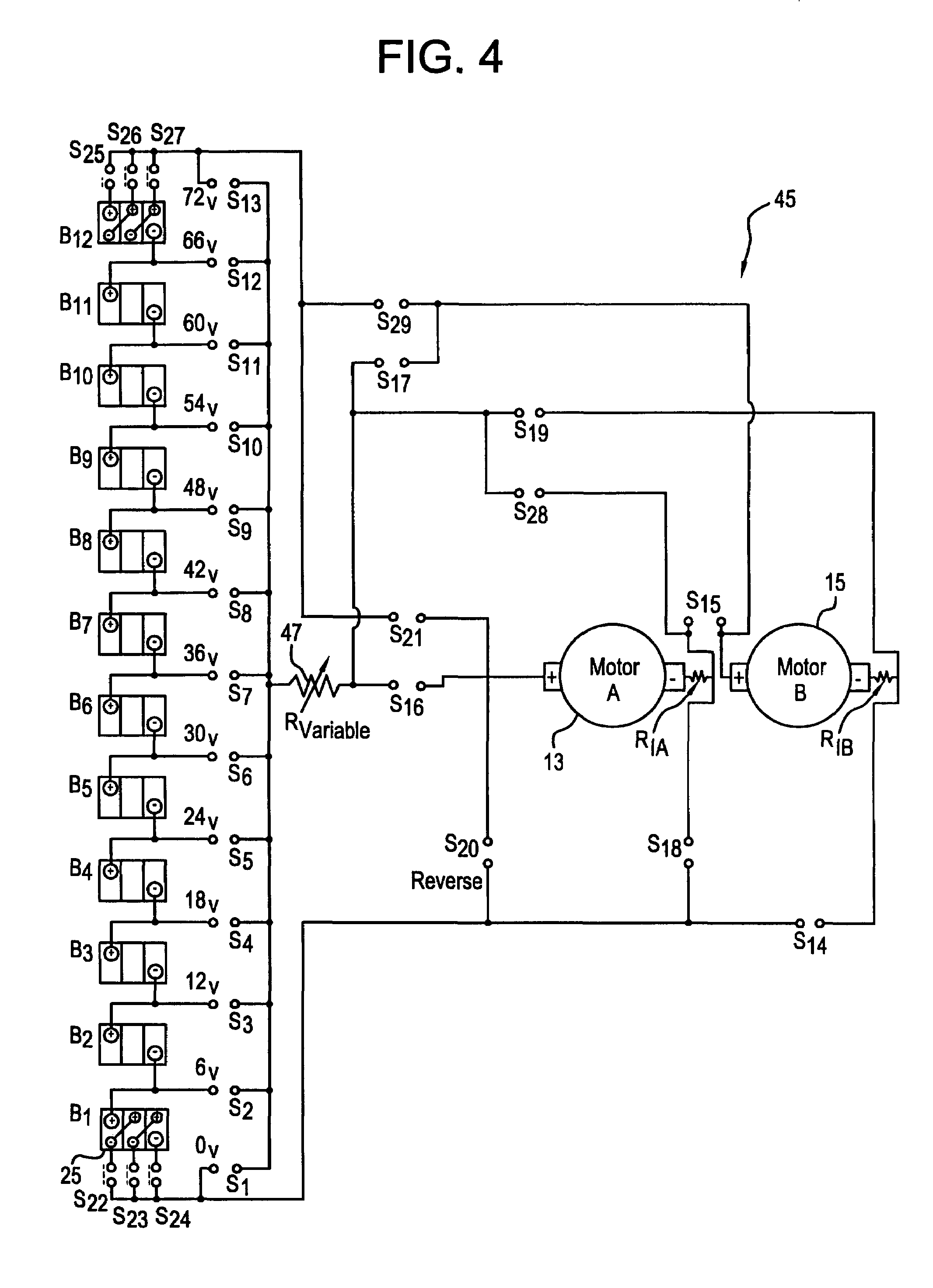
[0018]The present invention includes electric vehicle motors and control systems. One or more sets of wheels are connected by a drive shaft to two or more permanent magnet motor / regenerators ganged together. The motors are powered in series or parallel. Two or more batteries are connected in series. Shunted rectifier controls between batteries provide battery step control which reduces transients of switching by maintaining power from the previous battery until current starts to flow to the motors from the next battery and switch. A variable resistor and current sensor controls switching off for speed control between steps. The two or more motors are connected in series for increased torque at low speeds and are switched to a parallel configuration for maximum speed as speed increases.
[0019]Each set of driven wheels uses two or more permanent magnet motors grouped together. The battery step method control unit reduces transients to only one battery voltage value. The battery step method control unit is controlled by logic or a processor that monitors current and limits current according to set points dependent on operator input.
[0020]Regeneration is performed by the same battery step method control unit for reducing transients of switching. Top and bottom series switching is used for equalizing battery drain.

Problems solved by technology

Transients are limited to the effect of just one battery step by using rectifier shunt switching.
Until recently, powerful, lightweight permanent magnet motors were not available in sizes large enough for an automobile.
One problem is the lack of smooth control as one step is switched off and the next step is switched on.
Another problem is large transients as the motor is switched off before the next higher voltage step is switched on as the vehicle is accelerating.

Method used


Image

  • Electric vehicle motor and control system with high efficiency regeneration
  • Electric vehicle motor and control system with high efficiency regeneration
  • Electric vehicle motor and control system with high efficiency regeneration

Examples


Embodiment Construction

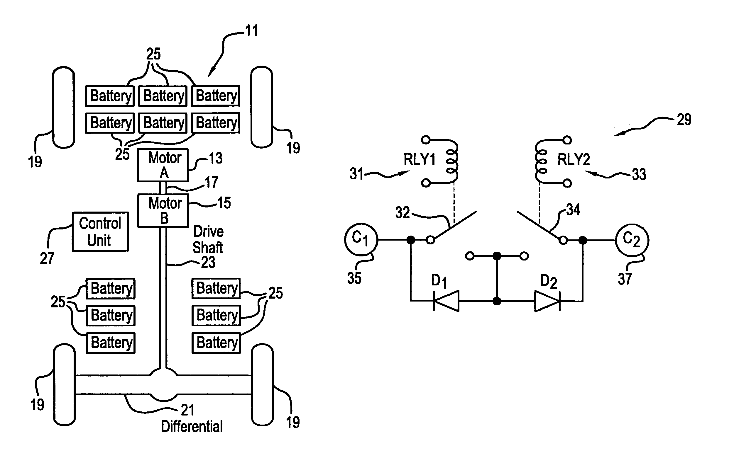
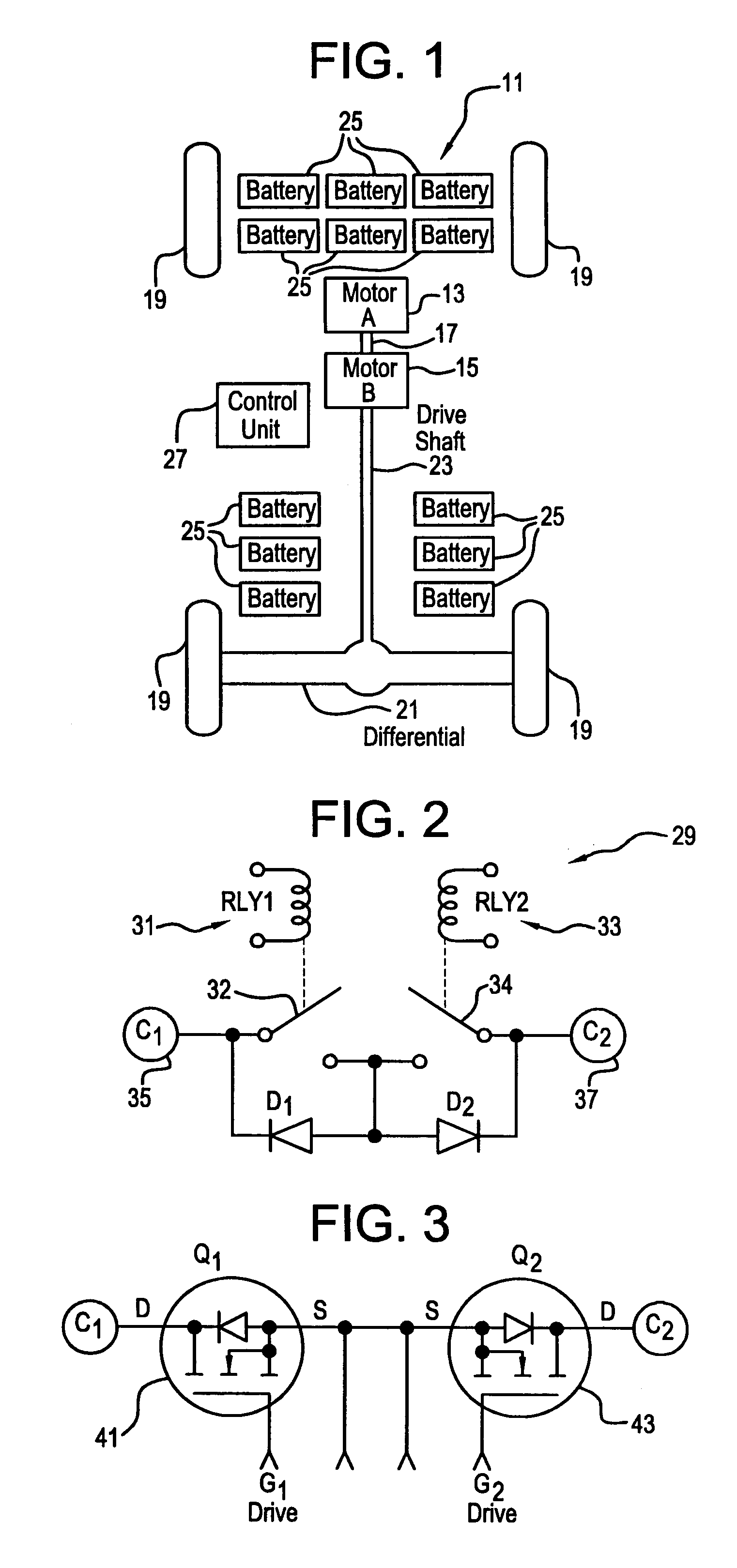
[0037]FIG. 1 is a schematic of a configuration of an automobile 11 with multiple motors 13, 15 that are mechanically coupled 17 together. Wheels 19 of the automobile 11 are connected by a differential 21 connected to the motors 13, 15 by a drive shaft 23. Multiple batteries 25 are located within the automobile 11. A control unit 27 controls the motors 13, 15.

[0038]FIG. 2 is a schematic representation of back-to-back rectifiers 29 with shunt switching. A mechanically or electromechanically switched system has relays 31, 33 and contactors 32, 34. The rectifiers directionally control current between switched points 35, 37 in the power line. Four switching modes are provided. The first is an open circuit when neither relay is energized and both contactors are open. The second is a short circuit when both relays are energized and both contactors are closed. The third is conduction through rectifier D2 passing current to the right, with relay 31 energized and contactor 32 closed. The four...


PUM


Abstract

The present invention is an electric vehicle power system that uses multiple permanent magnet motor / generators connected in series or parallel and multiple battery step switching. Motor, torque and speed are controlled by steps in series connection and then in parallel connection. Smooth acceleration, regeneration and current control are provided by delaying stepping from one battery step to the next until the next step is fully engaged. Transients are limited to the effect of one battery step by using rectifier shunt switching. Multiple motors provide acceleration torque at low speed in series connections and at cruising speeds in parallel connection. Regenerative deceleration is provided in the opposite manner. Battery depletion is averaged by flipping ends of a battery bank. Controls are provided with normal foot controls and a speed setter. A separate deceleration pedal or lever may be used.

Description

BACKGROUND OF THE INVENTION[0001]Electric vehicles have received limited acceptance among the general public in the United States.[0002]Two types of motors are most used for electric vehicles. These types include series wound D.C. motors, and A.C. induction motors.[0003]A series wound motor has good high starting torque characteristics, and is most commonly controlled by a variable duty cycle, high frequency chopping system. However, the series wound motor is a poor generator with no regeneration, unless the field coil is split from the series connection and changed to a parallel or shunt motor equivalent. Even then, the field consumes battery power, and there is no net regeneration power unless high rotational speeds can be maintained long enough to create a net benefit. Additionally, the duty cycle motor speed controller is not used for regeneration. A separate regeneration controller is needed for a series motor to gain any small possible regeneration power during deceleration. S...

Claims


Application Information

Patent Timeline
IPC IPC(8): H02P5/00
CPCB60L11/1805B60L11/1868B60L15/12H02P5/685B60L11/1855Y02T10/7005Y02T10/7066Y02T10/648Y02T10/646B60L50/52B60L58/19B60L58/20Y02T10/64Y02T10/70
Inventor EARLE, JOHN L.
Owner EARLE JOHN L
Learn More