
Wireless X-ray detector for a digital radiography system with remote X-ray event detection

a digital radiography and wireless technology, applied in the field of medical imaging, can solve the problems of low manufacturing yield, undue cost of cassettes, and the diodes themselves, and achieve the effects of improving the signal to noise ratio of the exposure detection circuit, detecting quickly and precisely, and more precise compensation of dark currents accumulated

Active Publication Date: 2007-05-01
CARESTREAM HEALTH INC
View PDF7 Cites 164 Cited by
  • Summary
  • Abstract
  • Description
  • Claims
  • Application Information

AI Technical Summary

Benefits of technology

[0011]An advantage of the invention lies in the ability to detect rapidly and precisely the cessation of X-ray exposure in a wireless digital radiography X-ray detector by improving the signal to noise ratio of the exposure detection circuit after onset of full X-ray exposure.
[0012]Another advantage is that knowing the exact time X-ray exposure ceases enables more precise compensation of dark currents accumulated in the pixels during the exposure interval. Precise compensation improves the image quality of the system

Problems solved by technology

The inclusion of the trigger diodes lowers manufacturing yields thereby making the cassettes unduly costly.
Also, the diodes themselves may be blocked by some radiation impervious portion of the object under test or may be out of the field of the radiation beam entirely.
A drawback is that the sensors must be read out continuously which consumes a relatively high amount of electrical power which can be a serious problem for a battery-power cassette operating independently of the main imaging system.
This approach, however, also consumes a high amount of power and is, therefore, a less than desirable solution.
However, the example disclosed in this application is limited to use with CMOS or CCD sensors and is not applicable to other types of sensors such as amorphous or crystalline silicon photodiodes or metal insulated semiconductor (MIS) sensors in extensive use in filmless imaging X-ray sensor panels.

Method used


Image

  • Wireless X-ray detector for a digital radiography system with remote X-ray event detection
  • Wireless X-ray detector for a digital radiography system with remote X-ray event detection
  • Wireless X-ray detector for a digital radiography system with remote X-ray event detection

Examples


Embodiment Construction

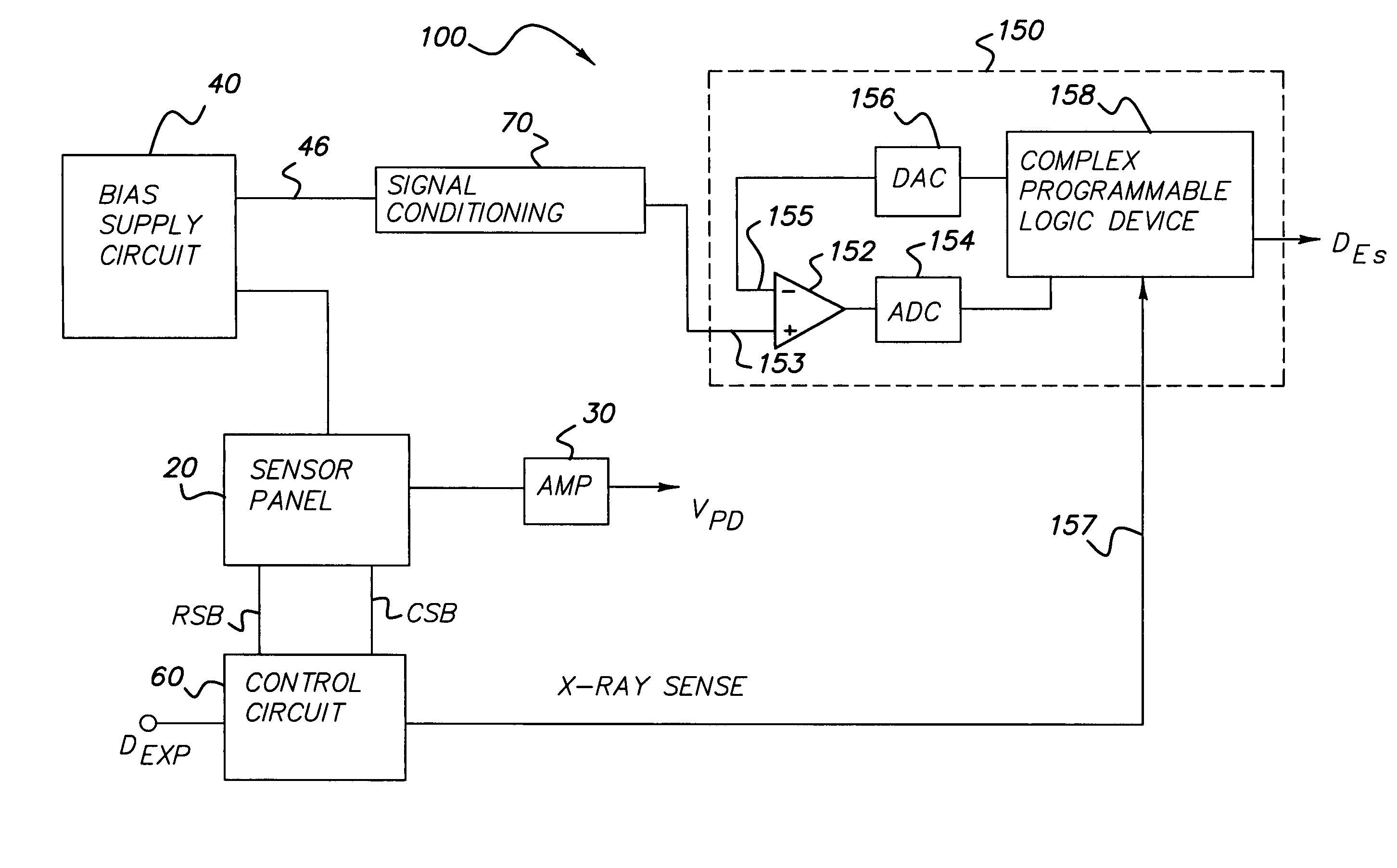
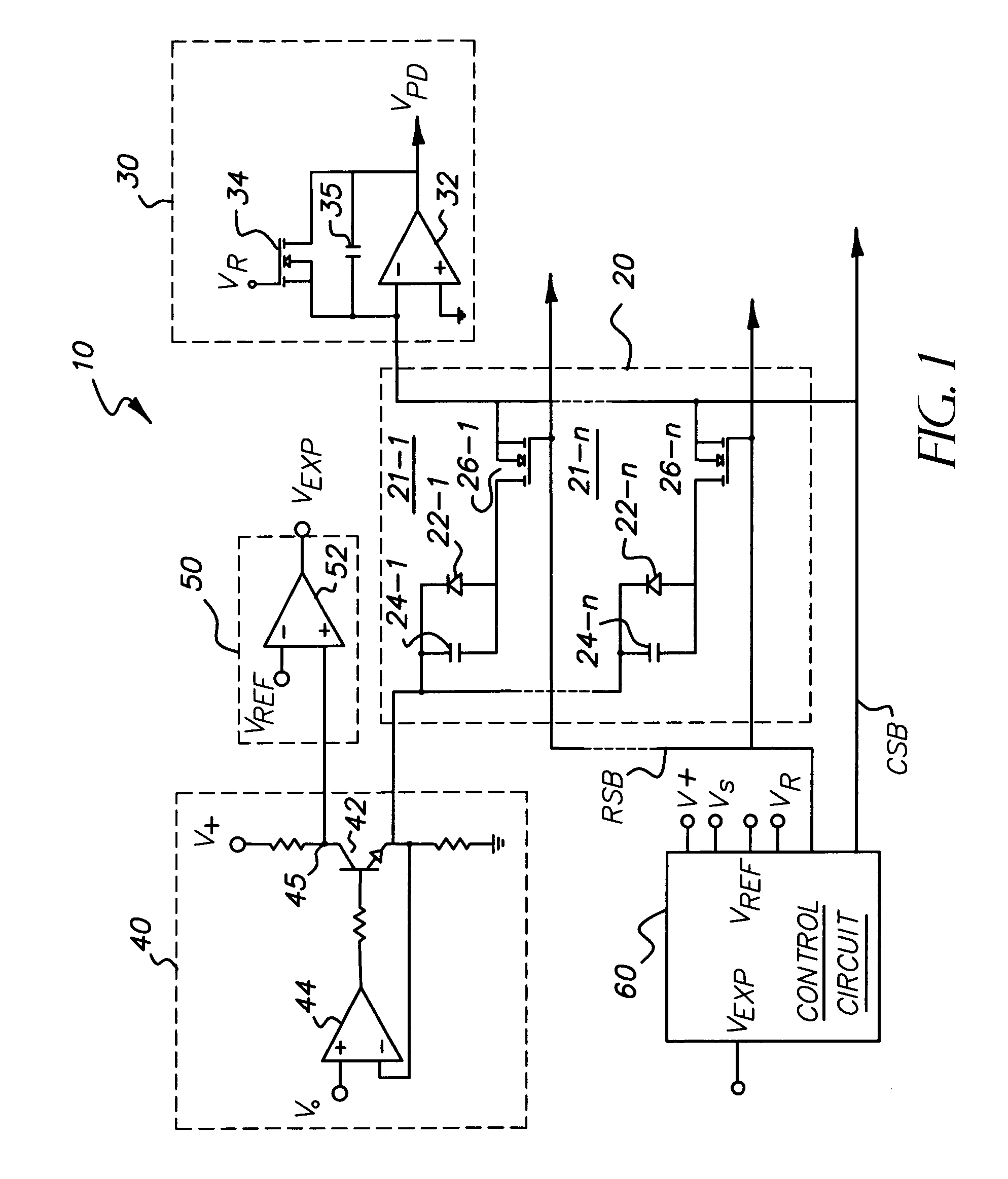
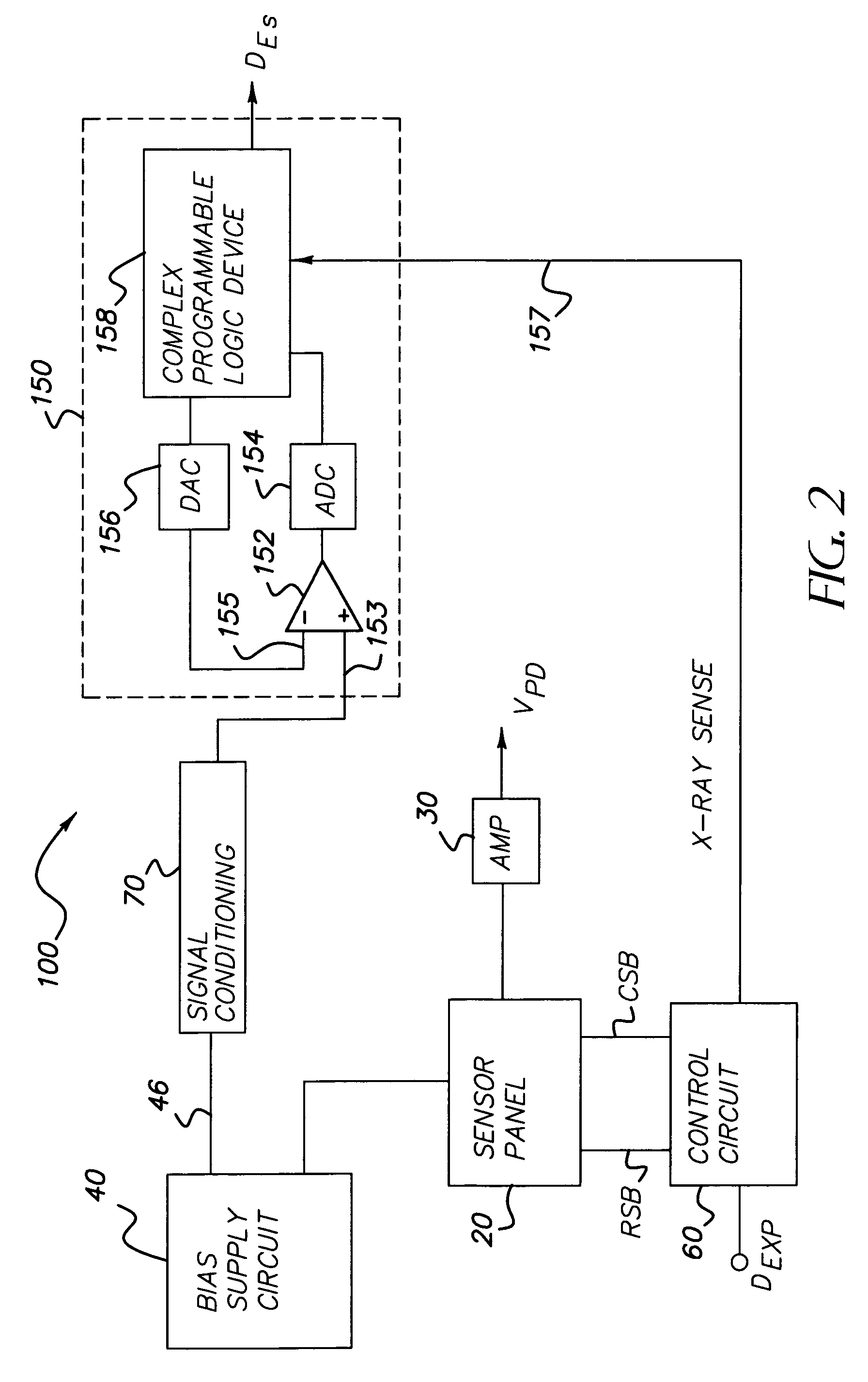
[0016]In FIG. 1, a wireless X-ray detector is shown which includes an X-ray sensor panel 20, a charge voltage photodetector output amplifier 30, a photodetector bias supply circuit 40, an X-ray exposure presence detector 50 and a control circuit 60.

[0017]Sensor panel 20 is of amorphous or crystalline silicon or metal insulated semiconductor material. Panel 20 includes a plurality of pixels 21 arrayed in a matrix of rows and columns. For convenience, only a single column of pixels 21-1 to 21-n is illustrated. Each pixel includes a photodiode 22 and a charge capacitor 24 for collecting charge from the photodiode during X-ray exposure. Typically, capacitor 24 consists of the inherent capacitance of the photodiode 22. The pixel further includes a solid state output switch 26 which is preferably a thin film field-effect transistor.

[0018]Amplifier 30 comprises a charge amplifier 32 adapted to output pixel photodiode signals VPD after each X-ray exposure. Additionally, the negative-positiv...


PUM


Abstract

A wireless X-ray detector for a digital radiography system with remote detection of impinging radiation from the system X-ray source onto a sensor panel having amorphous or crystalline silicon photodiodes or metal insulated semiconductor (MIS) sensors. Changes in current in the photodiode bias supply circuit is sensed to generate a signal indicating presence of radiation. Improved detection of X-ray cessation is achieved either by leaving at least one line of sensors connected between the bias supply circuit to a virtual ground during charge accumulation or by using an X-ray presence detector circuit that increases the sensitivity of the detector circuit to bias circuit current changes occurring after onset of the radiation.

Description

CROSS REFERENCE TO RELATED APPLICATIONS[0001]Reference is made to commonly assigned U.S. patent application Ser. No. 11 / 323,505, entitled “X-RAY IMPINGEMENT EVENT DETECTION SYSTEM AND METHOD FOR A DIGITAL RADIOGRAPHY DETECTOR”, filed on Dec. 30, 2005 in the names of Dhurjaty et al., incorporated herein by reference.FIELD OF THE INVENTION[0002]The invention relates generally to the field of medical imaging, and in particular to digital radiography. More specifically, the invention relates to a wireless X-ray detector for a digital radiography system employing remote X-ray event detection.BACKGROUND OF THE INVENTION[0003]Digital radiography is achieving a growing acceptance as an alternative to photographic-based imaging technologies that rely on photographic film layers to capture radiation exposure to produce and store an image of a subject's internal physical features. With digital radiography, the radiation image exposures captured on radiation sensitive layers are converted, pixe...

Claims


Application Information

Patent Timeline
IPC IPC(8): G01T1/24H05G1/60
CPCG01T1/247
Inventor DHURJATY, SREERAMYORKSTON, JOHN
Owner CARESTREAM HEALTH INC
Learn More