
Engine system and method of control

a technology of engine system and control method, applied in the direction of electric control, combustion engine, machine/engine, etc., can solve the problems of hcci having greater fuel efficiency and reducing nox production compared to other combustion modes, presenting various control problems, and limited combustion modes such as hcci

Inactive Publication Date: 2007-05-08
FORD GLOBAL TECH LLC
View PDF21 Cites 93 Cited by
  • Summary
  • Abstract
  • Description
  • Claims
  • Application Information

AI Technical Summary

Benefits of technology

[0006]In this way, in the HCCI mode of operation, the mass and temperature of air in the cylinder and the intake cam timing (e.g. the intake valve closing—IVC—angle) are varied to achieve a high or the highest possible fuel economy and / or emissions at the given engine speed and torque (e.g. as determined by the amount of fuel burned). Likewise, in the SI mode the spark timing and intake cam timing may be varied for the same purpose. To achieve smooth transients from one mode to another and reset the after treatment system if necessary, a set of operations may be performed that includes positioning the throttles and cam timing prior to the mode switch and restoring the optimal schedules appropriate for the new mode after the switch. This approach takes advantage of the relatively low sensitivity to the IVC of the amount of air trapped in the cylinder when IVC is close to TDC relative to the sensitivity when IVC is close to the middle of the compression stroke. Thus, this approach is enabled by the longer duration of the dominant (cold stream) intake valve in the SI mode compared to the valve duration(s) in the HCCI mode. By varying the valve timing of at least one of the intake valves, the absolute amount of air and / or the initial charge temperature may be rapidly varied, thereby providing improved operation when changing combustion modes. Further, by providing at least some heated air during a spark ignition mode, a ready reserve of heated air may be maintained.
[0008]In another embodiment, the method may further include varying an amount of fuel delivered to the cylinder during the transition in response to the varied timing. In this way, it is possible to account for the variation in fuel pushback during the timing variation of the transition.

Problems solved by technology

In some conditions, HCCI may have greater fuel efficiency and reduced NOx production compared to other combustion modes.
However, combustion modes such as HCCI may be limited under some conditions, since a substantial amount of heat and pressure may be needed to produce combustion.
Further, transitions into and out of the HCCI mode may present various control issues.
However, the inventors herein have recognized a disadvantage with such an approach.
For example, during the transient conditions of SI / HCCI transitions in the above system, the cylinders may experience incorrect cylinder air amounts, residual amounts, and / or fuel charge amounts.

Method used


Image

  • Engine system and method of control
  • Engine system and method of control
  • Engine system and method of control

Examples


Embodiment Construction

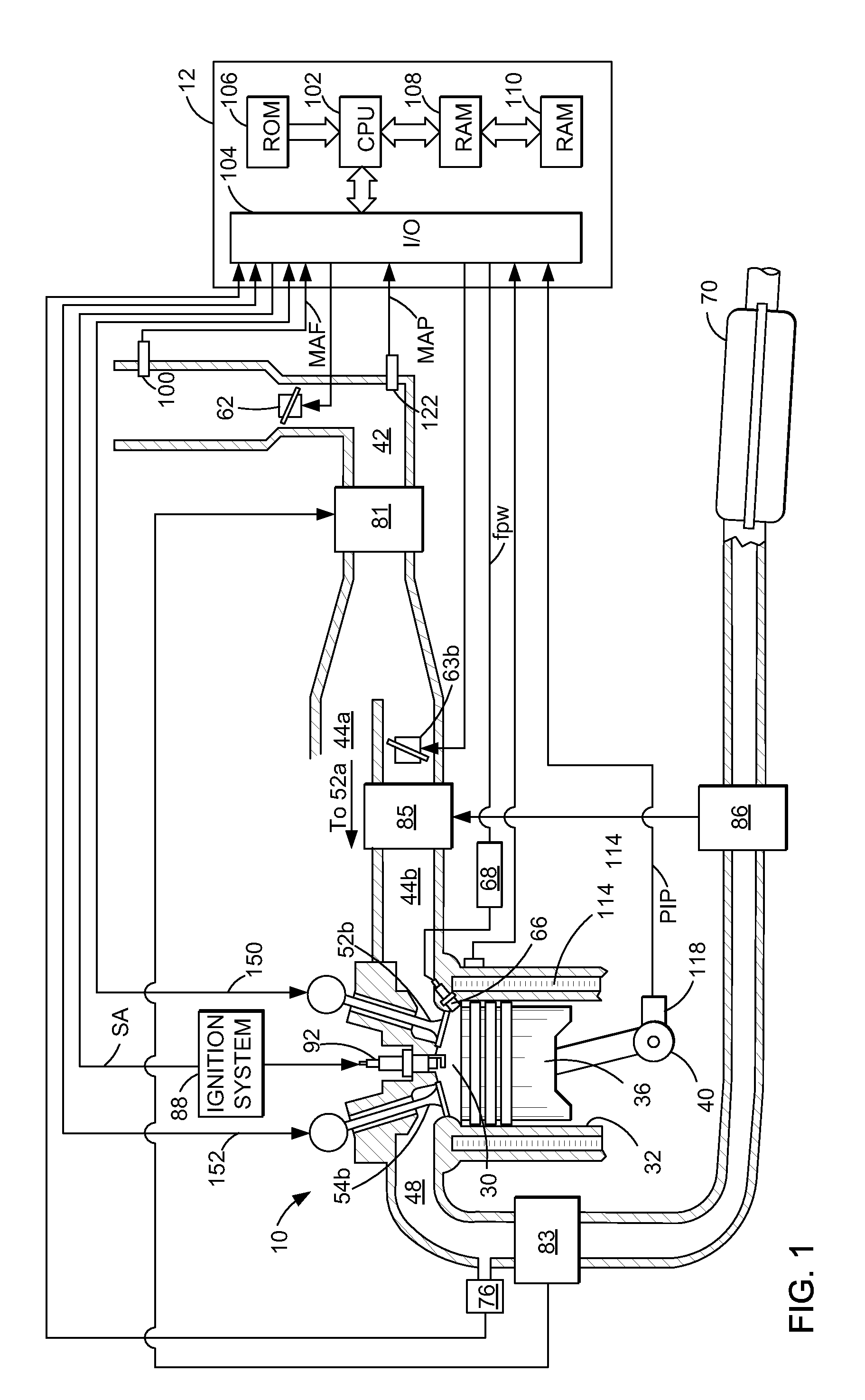
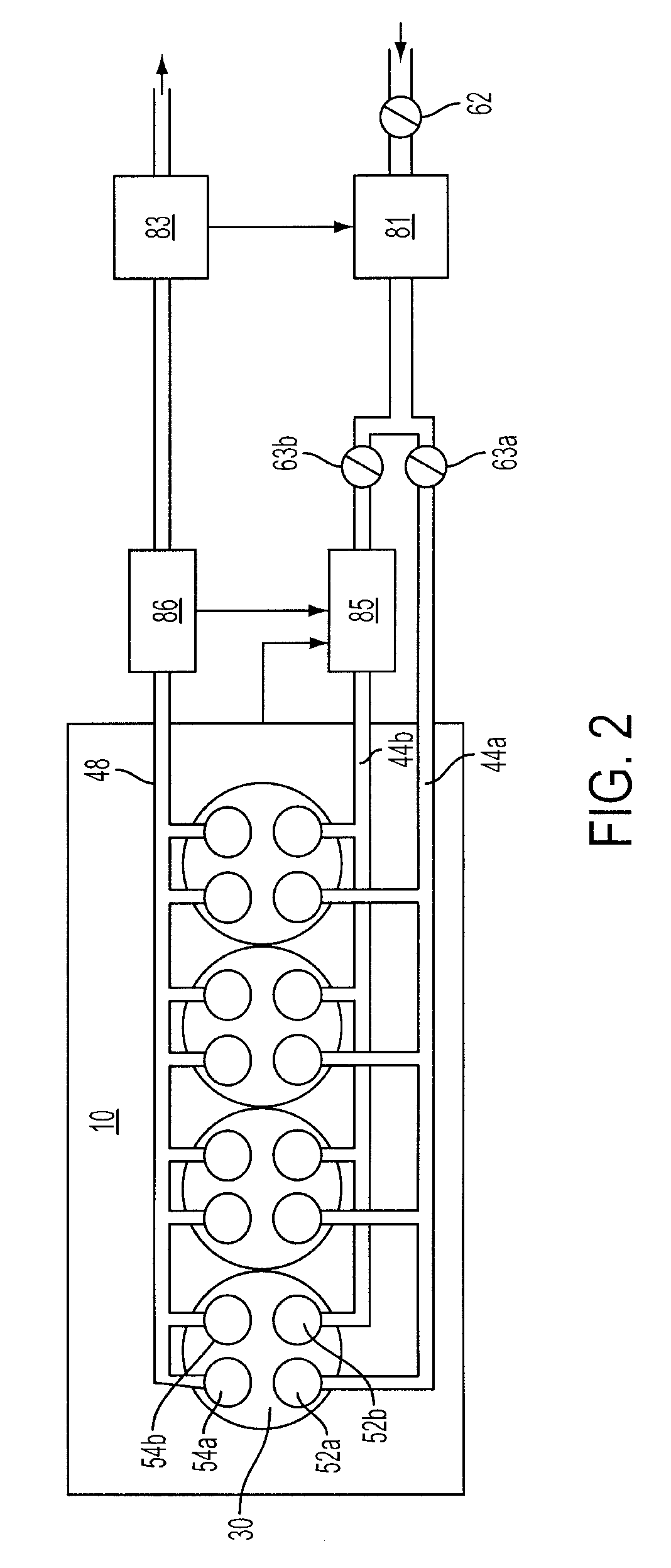
[0017]FIG. 1 is a schematic diagram of one cylinder of a multi-cylinder engine, as well as one of the intake and exhaust paths connected to that cylinder. A direct injection internal combustion engine 10, comprising a plurality of combustion chambers, is controlled by a control system including electronic engine controller 12. Combustion chamber 30 of engine 10 is shown including combustion chamber walls 32 with piston 36 positioned therein and connected to crankshaft 40. A starter motor (not shown) may be coupled to crankshaft 40 via a flywheel (not shown). Combustion chamber 30 is shown communicating with intake manifold 44b and exhaust manifold 48 via respective intake valve 52b and exhaust valve 54b. Combustion chamber 30 also may communicate with intake manifold 44a and exhaust manifold 48 via respective intake valve 52a and exhaust valve 54a (shown in FIGS. 2 and 3). As will be described below in greater detail, intake air may be delivered to combustion chamber 30 via valve 52...


PUM


Abstract

A method of operating an engine having a hotter and colder airstreams separately controlled to a cylinder is provided. The method controls valve timing during a transition in operating modes to provide improved operation.

Description

FIELD[0001]The present application relates to systems and methods for control of intake air during mode transitions with an internal combustion engine.BACKGROUND AND SUMMARY[0002]Internal combustion engines may operate in a variety of combustion modes. One example mode is homogeneous charge compression ignition (HCCI), wherein an air and fuel mixture achieves a temperature where combustion occurs by autoignition without requiring a spark being performed by a sparking device. In some conditions, HCCI may have greater fuel efficiency and reduced NOx production compared to other combustion modes. However, combustion modes such as HCCI may be limited under some conditions, since a substantial amount of heat and pressure may be needed to produce combustion. Further, transitions into and out of the HCCI mode may present various control issues.[0003]One approach to enable operation in a variety of combustion modes is described in U.S. 2005 / 0183693. In this example, a cylinder with cam prof...

Claims


Application Information

Patent Timeline
Patent Type & Authority Patents(United States)
IPC IPC(8): F02B11/00
CPCF02D37/02F02D41/3035F02D41/3064F02D41/0235F02D2041/001Y02T10/128Y02T10/12
Inventor JANKOVIC, MRDJAN
Owner FORD GLOBAL TECH LLC
Learn More