Collector for EUV light source

a light source and collector technology, applied in the field of softxray light generation, can solve the problems that the mo/si/c/ru multi-layer stack cannot meet the theoretically calculated reflectivity expectation, and achieve the effect of low high probability of sputtering the second material

Inactive Publication Date: 2007-05-15
ASML NETHERLANDS BV
View PDF65 Cites 62 Cited by
  • Summary
  • Abstract
  • Description
  • Claims
  • Application Information

AI Technical Summary

Benefits of technology

[0119]Applicants have also examined the effectiveness of electrostatic protection of the collector mirror. The concept has been proposed in the literature, i.e., to generate an electric field between the source LPP and the collector mirror such that the energetic ions must climb up a potential well as they travel toward the mirror. This potential well can be made deep enough that the ions loose all of their kinetic energy before reaching the mirror. In fact, they are turned around and sent packing back down the potential well, never reaching the mirror. Applicants have discovered, however, that attempting to do this by running an electrical connection through the vessel to the collector mirror was ineffective due to the target bias dropping to near zero upon pulsing the laser, which was determined to be the result of a high peak current required to maintain the bias voltage and the large lead wire required, thus dropping all of the voltage along the inductance of the wire. To correct this problem applicants then installed capacitors inside the vacuum vessel and constructed low inductance buss work between ground and the target plate. Inductance was measured by placing a copper sheet up and around the target and attached to ground. By charging the capacitors to a low voltage and discharging them by pressing the copper sheet against the target applicants measured the ringing voltage waveshape and inferred the inductance. The result was 104 nH with a 697 ns half-period discharge waveshape. This discharge period is much longer than the laser pulse and subsequent EUV emission initially causing concern whether the bias could be maintained during the critical period when the ions are created and leave the plasma region (˜20 ns). Applicants determined, however, that such short time scales were unimportant. What is important is, e.g., to maintain or reestablish the target bias, e.g., in a time scale that is, e.g., short compared with the travel time of the ions from the target to the mirror. With the present geometries the ion travel time is about 2.5 μs, so a circuit half-period of 0.7 μs should be sufficient.

Problems solved by technology

However, Braun also finds that the Mo / Si / C / Ru multi-layer stacks do not live up to theoretical calculated reflectivity expectation, probably due to an initial Mo layer deposition surface roughness that propagates upward through the stack.

Method used


Image

  • Collector for EUV light source
  • Collector for EUV light source
  • Collector for EUV light source

Examples


Embodiment Construction

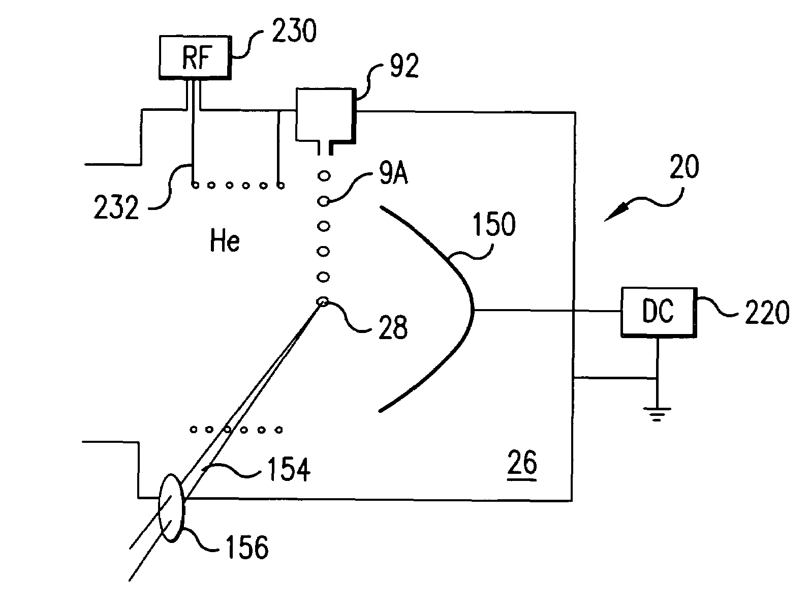
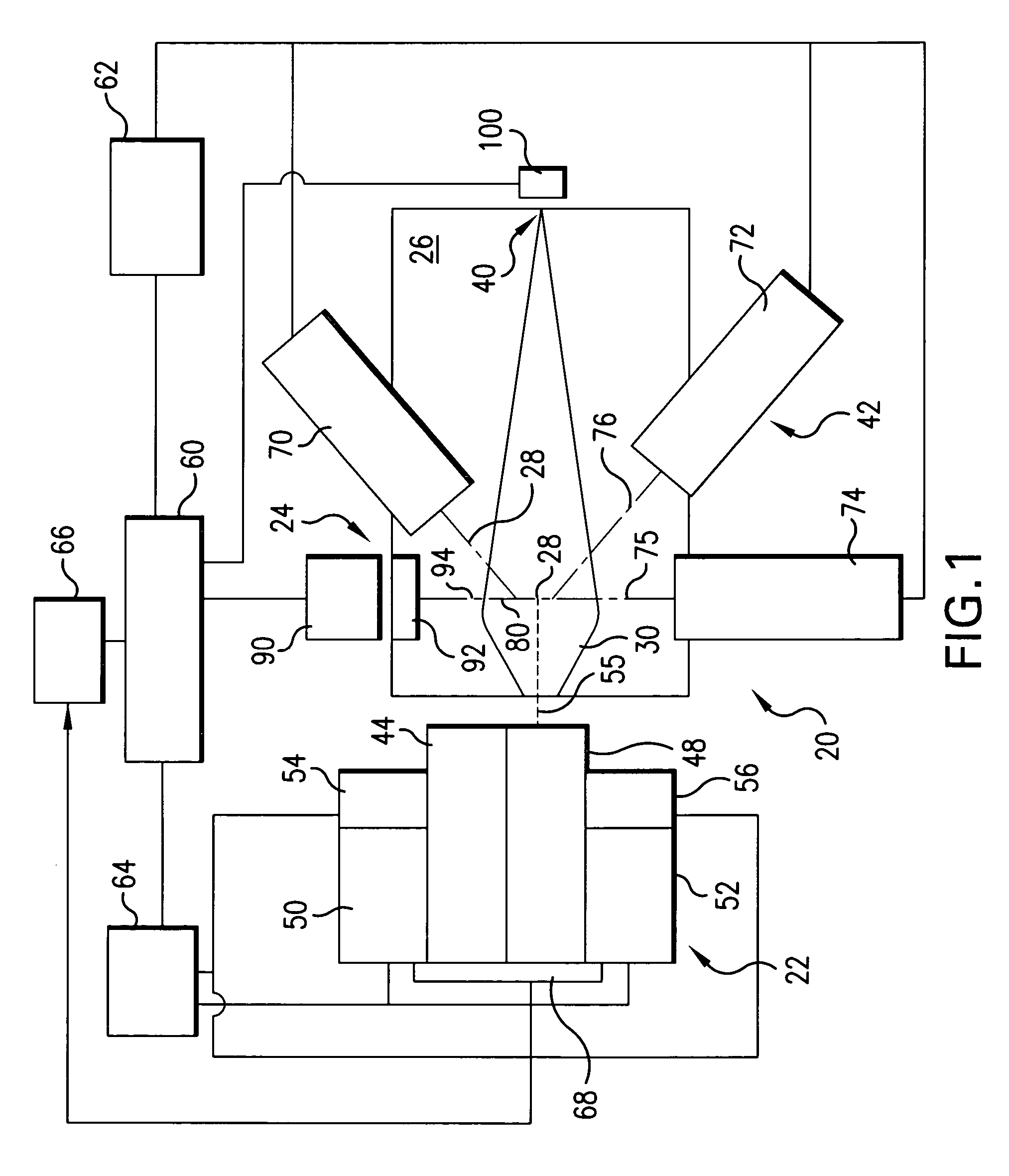
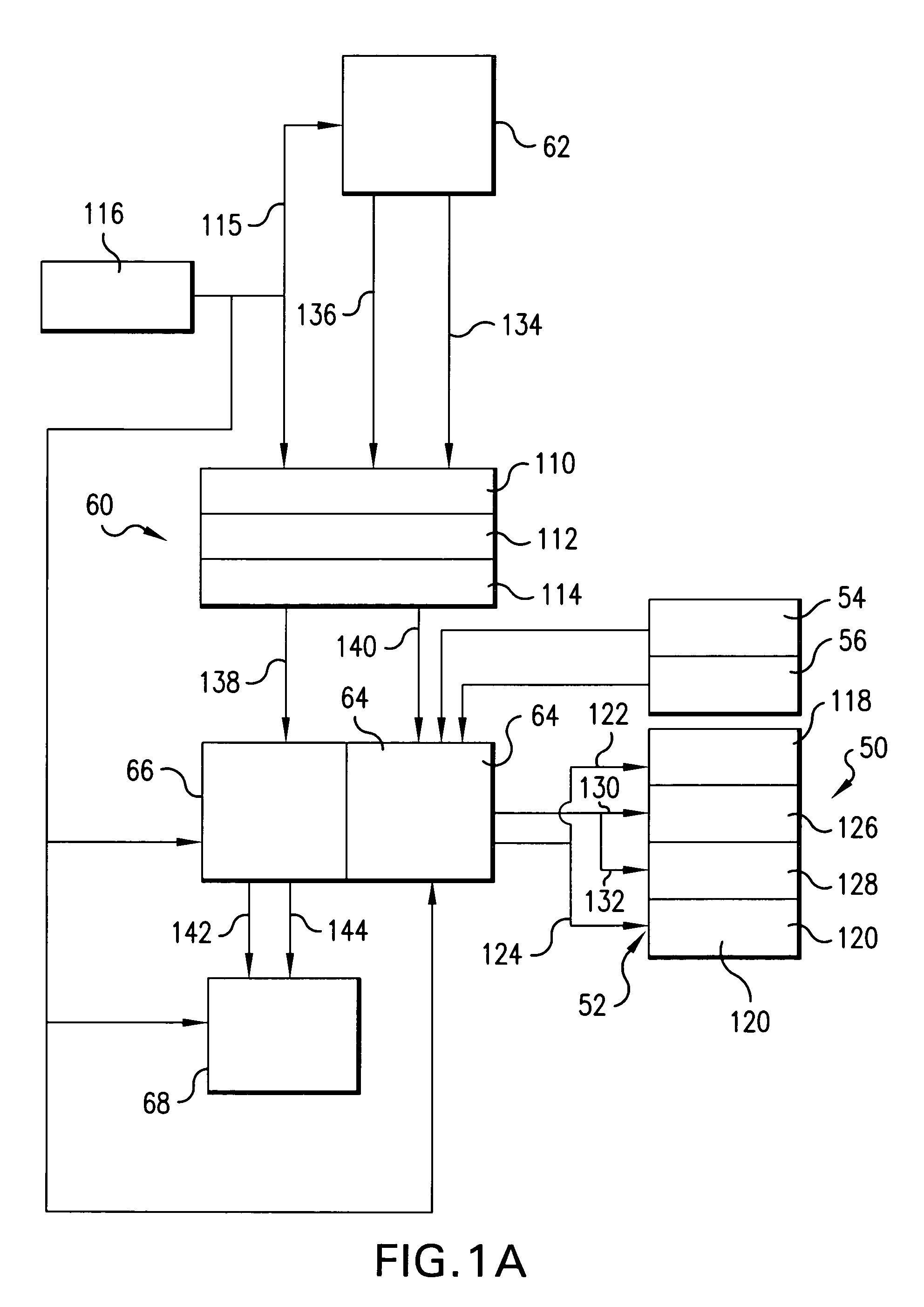
[0035]Turning now to FIG. 1 there is shown a schematic view of an overall broad conception for an EUV light source, e.g., a laser produced plasma EUV light source 20 according to an aspect of the present invention. The light source 20 may contain a pulsed laser system 22, e.g., a gas discharge laser, e.g., an excimer gas discharge laser, e.g., a KrF or ArF laser operating at high power and high pulse repetition rate and may be a MOPA configured laser system, e.g., as shown in U.S. Pat. Nos. 6,625,191, 6,549,551, and 6,567,450. The laser may also be, e.g., a solid state laser, e.g., a YAG laser. The light source 20 may also include a target delivery system 24, e.g., delivering targets in the form of liquid droplets, solid particles or solid particles contained within liquid droplets. The targets may be delivered by the target delivery system 24, e.g., into the interior of a chamber 26 to an irradiation site 28, otherwise known as an ignition site or the sight of the fire ball. Embodi...


PUM

PropertyMeasurementUnit
temperatureaaaaaaaaaa

Abstract

A method and apparatus for debris removal from a reflecting surface of an EUV collector in an EUV light source is disclosed which may comprise the reflecting surface comprises a first material and the debris comprises a second material and / or compounds of the second material, the system and method may comprise a controlled sputtering ion source which may comprise a gas comprising the atoms of the sputtering ion material; and a stimulating mechanism exciting the atoms of the sputtering ion material into an ionized state, the ionized state being selected to have a distribution around a selected energy peak that has a high probability of sputtering the second material and a very low probability of sputtering the first material. The stimulating mechanism may comprise an RF or microwave induction mechanism.

Description

RELATED APPLICATIONS[0001]This application is a continuation-in-part of U.S. Ser. No. 10 / 409,254 filed Apr. 8, 2003, now U.S. Pat No. 6,972,421 the disclosure of which is incorporated by reference herein.FIELD OF THE INVENTION[0002]The present invention relates to the field of the generation of EUV (soft-x-ray) light for such applications as semiconductor integrated circuit lithography exposure light sources, and more particularly to light collectors for such devices.BACKGROUND OF THE INVENTION[0003]The need for such applications as ever increasingly smaller critical dimensions for semiconductor integrated circuit manufacturing the need has arisen to move from the generation of Deep Ultraviolet (“DUV”) light to Extreme Ultraviolet (“EUV”) light, also referred to as soft-x-ray light. Various proposals exist for apparatus and methods for the generation of such light at effective energy levels to enable, e.g., adequate throughput in an EUV lithography tool (e.g., a stepper scanner or s...

Claims


Application Information

Patent Timeline
Patent Type & Authority Patents(United States)
IPC IPC(8): H01J35/20G02B5/00G03F7/20G21C11/00G21K1/06H01J1/50
CPCB82Y10/00G03F7/70033G03F7/70175G03F7/70916G21K1/062H05G2/001H01S3/10
Inventor PARTLO, WILLIAM N.ALGOTS, JOHN MARTINBLUMENSTOCK, GERRY M.BOWERING, NORBERTERSHOV, ALEXANDER I.FOMENKOV, IGOR V.PAN, XIAOJIANG
Owner ASML NETHERLANDS BV
Why Eureka
Try Eureka